Milking installation with milk pump

a technology of installation and milk pump, which is applied in the direction of flexible member pump, positive displacement liquid engine, thin material handling, etc., can solve the problems of lypolysis and the creation of free fatty acids in the milk, the volume of milk will always remain, and the undesirable effect of pumping, etc., to solve or reduce the problem of lypolysis, effective cleaning and service, and less cumbersome assembly and operation

Active Publication Date: 2016-08-23
LELY PATENT
View PDF22 Cites 0 Cited by
  • Summary
  • Abstract
  • Description
  • Claims
  • Application Information

AI Technical Summary

Benefits of technology

[0009]It is thus an object of the invention to provide a milk pump in a milking installation that solves or reduces the problem of lypolysis associated with the centrifugal pumping of milk without the drawbacks of the known solution. It is further an object of the invention to provide a milk pump in a milking installation in which no or hardly any milk is left behind at the end of a pumping stroke or pumping action. It is further an object of the invention to provide a milk pump in a milking installation which can be effectively cleaned and serviced. It is also an object of the present invention to provide alternative structures which are less cumbersome in assembly and operation and which moreover can be made relatively inexpensively. Alternatively it is an object of the invention to at least provide the public with a useful choice.

Problems solved by technology

A drawback of the centrifugal pump is that such pumps damage the membrane surrounding the fat globules of the milk causing lypolysis and the creation of free fatty acids in the milk.
This is an undesirable effect of pumping.
A drawback of the pump disclosed in GB2192673 is the fact that the pump cannot completely empty the chambers and thus a volume of milk will always remain inside the pump.
Milk being an easily degradable fluid and also being susceptible to growth of spoilage organisms such as microbacteria, yeast and molds, it is highly undesirable to have a residual volume of milk present in the milk pump.
The fluid remaining in the pump also prevents effective cleaning of the pump taking place.
This contaminates milk with chemicals which again is undesirable.

Method used


Image

  • Milking installation with milk pump
  • Milking installation with milk pump
  • Milking installation with milk pump

Examples


Embodiment Construction

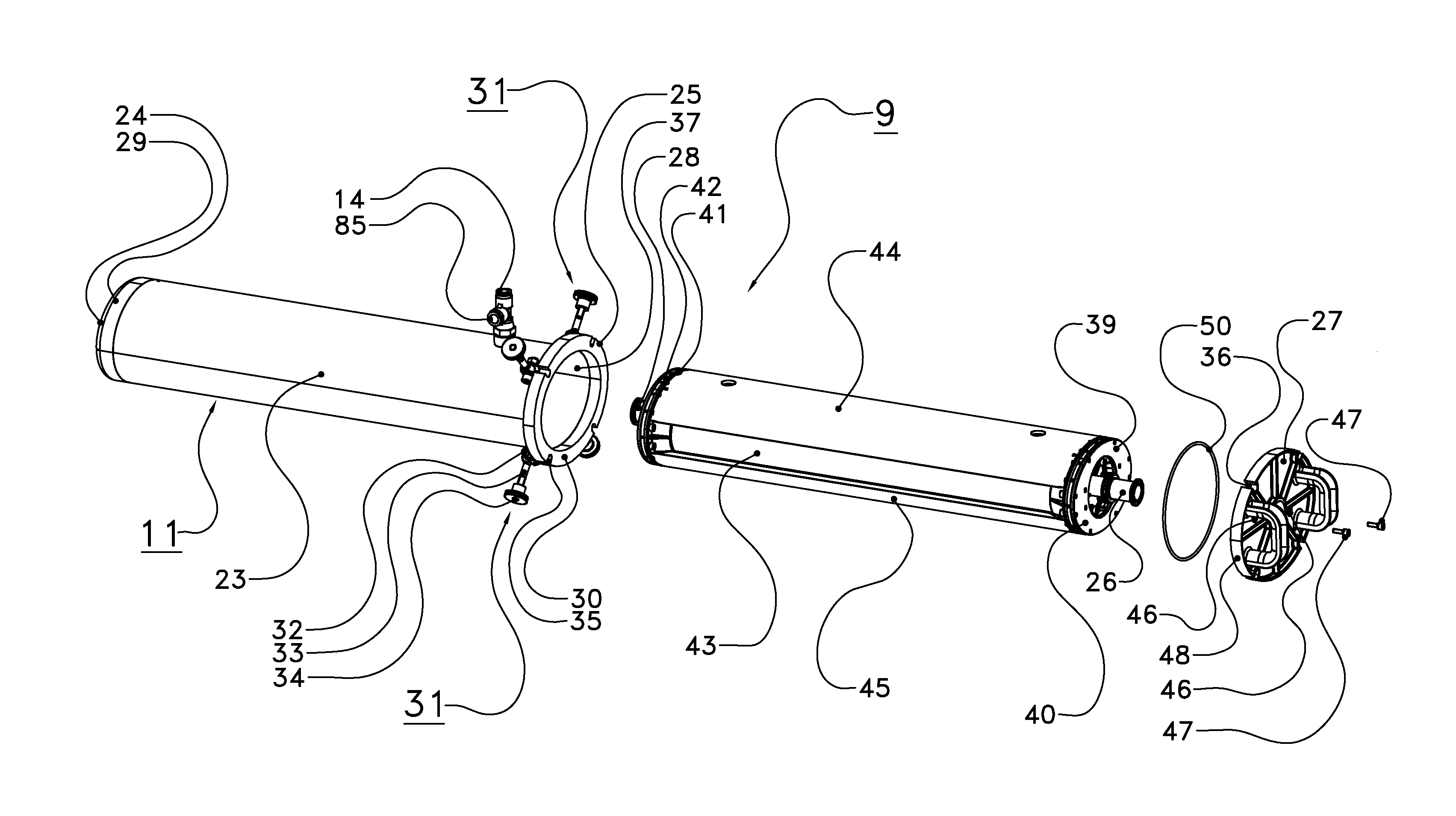
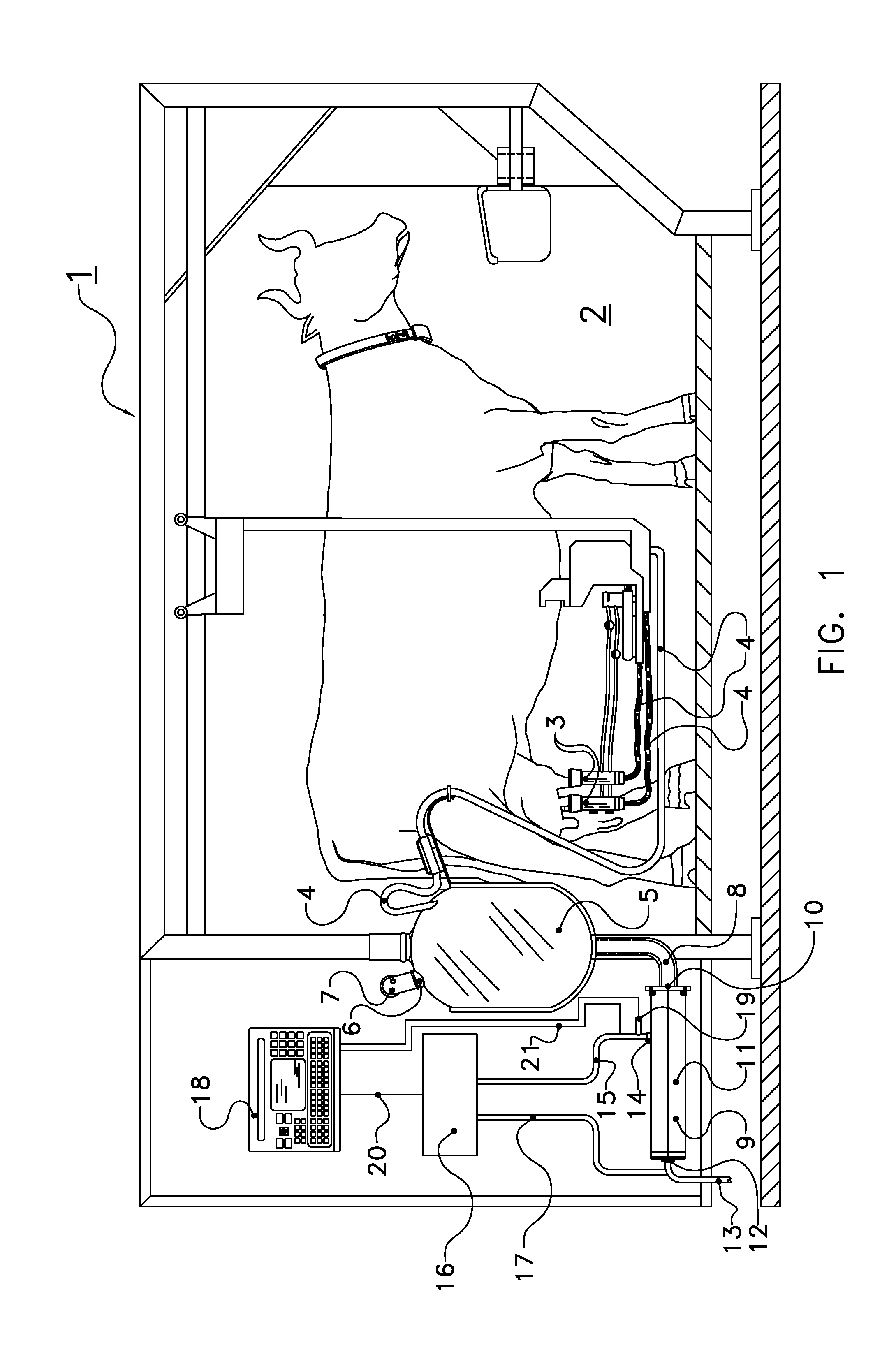
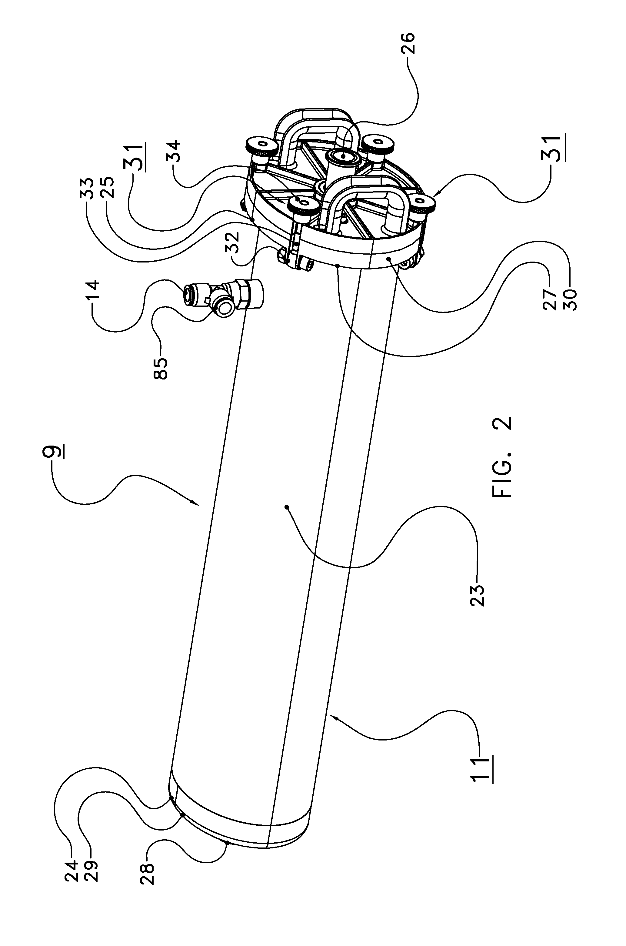
[0040]The following is a description of certain embodiments of the invention, given by way of example only and with reference to the drawings. FIG. 1 shows a milking installation 1 provided with a milking robot 2 for automatically connecting teat cups 3 to the teats of a dairy animal. Milk lines 4 extend between the teat cups and a milk de-aeration unit or milk glass 5. A de-aeration port 6 is present at the top of the de-aeration unit and a de-aeration line 7 connects the milk glass to a vacuum system (not shown). At the bottom of the milk glass a milk inlet line 8 is provided which connects the milk glass to the milk pump 9. The milk pump includes a milk inlet 10, a pump housing 11, a milk outlet 12. A further milk outlet line 13 is connected to the milk outlet 12 which leads to a milk storage unit or milk separation units (not shown). Generally the outlet can be branched and a manifold can be interposed such that milk can be separated out to several milk containers. Thus e.g. col...


PUM


Abstract

A milking installation with a milking robot for automatically connecting teat cups to the teats of a dairy animal has milk lines extending between the teat cups and a milk de-aeration unit or milk glass. A de-aeration port is present at the top of the de-aeration unit and a de-aeration line connects the milk glass to a vacuum system. At the bottom of the milk glass a milk inlet line is provided which connects the milk glass to the milk pump. The milk pump includes a milk inlet, a pump housing, a milk outlet. The milk pump is a membrane pump which type of pump is known to be gentle to the milk and thus reduce occurrence of lypolysis of the milk when pumped through the milking installation.

Description

CROSS REFERENCE TO RELATED APPLICATIONS[0001]This application is a continuation of PCT application number PCT / 2011 / 000065 filed on 22 Sep. 2011, which claims priority from Netherlands application number 1039329 filed on 25 Oct. 2010. Both applications are hereby incorporated by reference in their entireties.BACKGROUND OF THE INVENTION[0002]1. Field of the Invention[0003]The invention relates to a milking installation with a milk pump.[0004]2. Description of the Related Art[0005]Milking installations generally include at least one set of teat cups with a plurality of teat cups through which milk flows under vacuum to a temporary storage and milk de-aeration unit e.g. a milk glass and a pump to transport the milk from the milk glass to an accumulating storage tank or to other containers. Such pumps generally are centrifugal pumps.[0006]A drawback of the centrifugal pump is that such pumps damage the membrane surrounding the fat globules of the milk causing lypolysis and the creation o...

Claims


Application Information

Patent Timeline
Patent Type & Authority Patents(United States)
IPC IPC(8): A01J5/04F04B43/113F04B43/08
CPCA01J5/042F04B43/084F04B43/113F04B43/08Y10T137/85978
Inventor MOSTERT, GERARDVAN DE WALLE, JACOBUS IZAAKDOUZOULIKOPOULOS, DIMITRIS
Owner LELY PATENT
Why Eureka
Try Eureka