
Gas generator with hybrid spring

Inactive Publication Date: 2008-06-19
JOYSON SAFETY SYST ACQUISITION LLC
View PDF6 Cites 6 Cited by
  • Summary
  • Abstract
  • Description
  • Claims
  • Application Information

AI Technical Summary

Benefits of technology

[0007]It is an object of the present invention to provide a gas generator having a spring / cushion combination provided at either or both ends of the propellant wafer stack, within the inflator, thereby providing an effective cushion relative to required drop testing now included in airbag system specifications. The spring / cushion combination may be incorporated in any type of gas generator that incorporates a gas generant charge, whereby the integrity of the shape of the charge is preserved or better maintained by the enhanced cushioning of the annular spring / cushion combination.

Problems solved by technology

These systems have made significant contributions to automobile safety, however, as with the addition of any standard feature, they increase the cost, manufacturing complexity and weight of most vehicles.
In particular, the gas generator or inflator used in many occupant restraint systems tends to be the heaviest, most complex component.
Because many inflators utilize pyrotechnic gas generant compounds to produce inflation gas for the associated airbag, the inflator structure is necessarily robust, making such inflators correspondingly heavy.
Such inflator bodies can be quite heavy, and the manufacturing process is relatively complicated given processing steps necessary to secure the internal partitions.

Method used


Image

  • Gas generator with hybrid spring
  • Gas generator with hybrid spring
  • Gas generator with hybrid spring

Examples


first embodiment

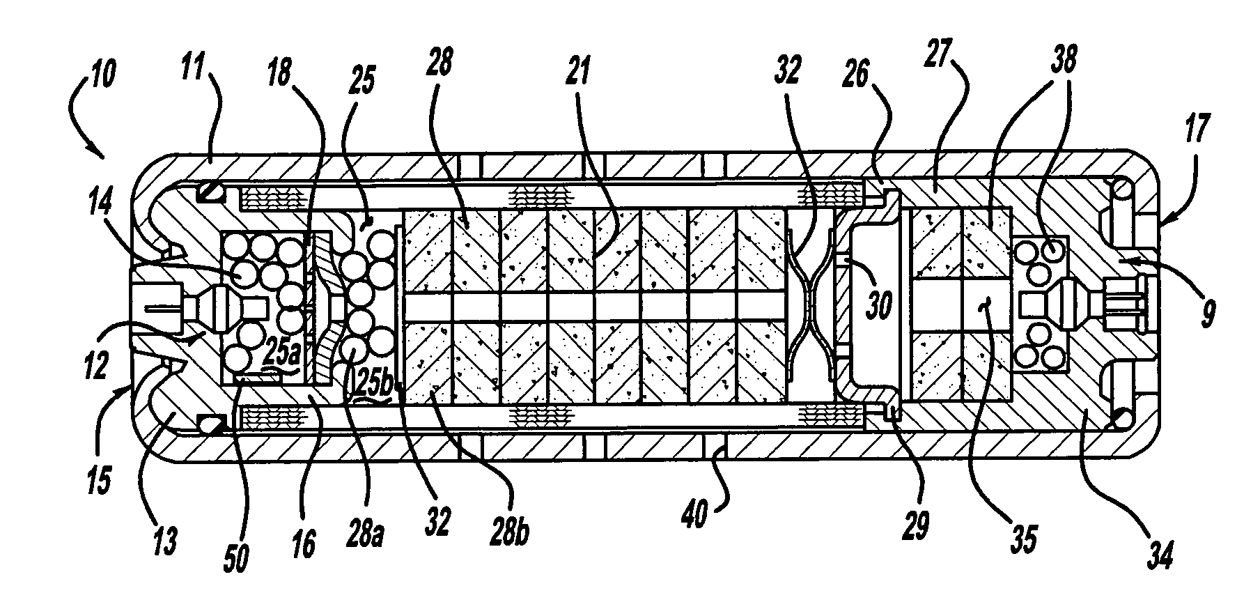
[0012]Referring to FIG. 1, there is shown a gas generator or inflator 10 according to a Inflator 10 is designed for use with an inflatable restraint system in an automobile, supplying inflation gas for inflation of a conventional airbag cushion, a function well known in the art. Exemplary inflator 10 utilizes two propellant charges, described herein, that are ignited in separate combustion chambers, and discharge inflation gas via a common plenum 21. Inflator 10 further provides independently operable initiators for igniting the respective propellant charges, imparting significant variation to the available operating schemes for the inflator. For instance, both sequential and serial firing of the two charges is possible, depending on the optimal deployment of the associated airbag. It is contemplated that inflator 10 will find greatest utility in passenger-side airbag systems; however, other applications are possible without departing from the scope of the present invention. All th...

second embodiment

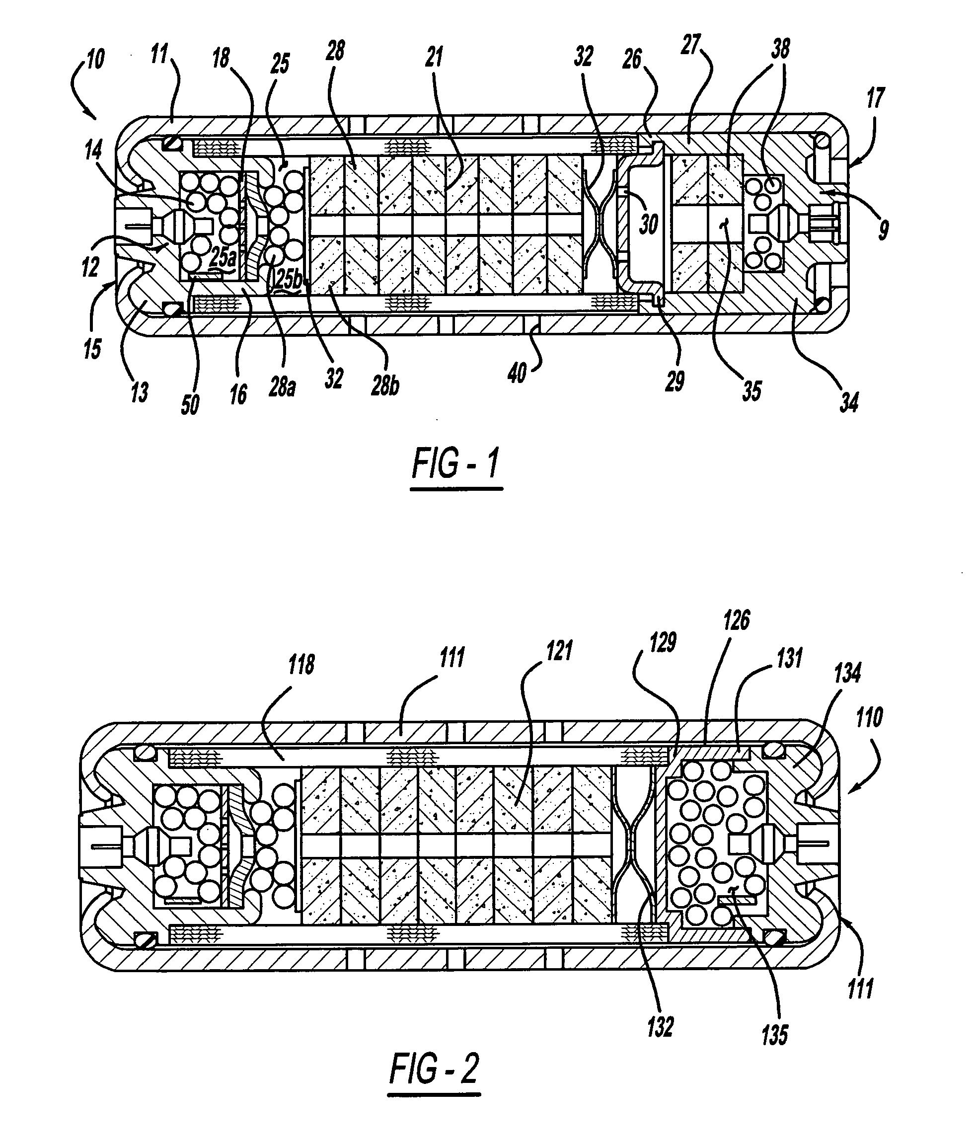
[0025]Referring now to FIG. 2, there is shown an inflator 110 according to the present invention. Inflator 110 shares many features with previously described inflator 10, however, there are significant differences. Referring in particular to an end region 117 of inflator 110, included therein is a partitioning assembly 126. Partitioning assembly 126 includes a cap 129 that is preferably press-fit onto an end closure 134, in turn secured to an inflator body 111. Cap 129 and end closure 134 are both preferably metallic, however, they might be formed from some other material, for instance a polymer, without departing from the scope of the present invention. The outer diameter of cap 129 is preferably less than the inner diameter of inflator body 110 such that gas can flow through the gap between the two, as described herein. Cap 129 preferably includes a substantially cylindrical first portion 131 having a first diameter, and a substantially cylindrical second portion 132 having a seco...


PUM


Abstract

The present invention provides an inflator for an inflatable restraint system in an automobile, or more generally, a gas generator. The inflator includes an inflator body having a plurality of inflation apertures and defining a first combustion chamber wherein a first propellant charge is positioned. At least one annular spring containing a cushion is provided for maintaining the integrity of the shape of the propellant charge.

Description

CROSS-REFERENCE TO RELATED APPLICATIONS[0001]This application claims the benefit of U.S. Provisional Application Ser. No. 60 / 875,302 filed on Dec. 15, 2006.TECHNICAL FIELD[0002]The present invention relates generally to pyrotechnic gas generators for inflatable restraint devices, and more particularly to such a gas generator having at least one annular spring and a cushion contained within the annular spring.BACKGROUND OF THE INVENTION[0003]Inflatable restraint systems or “airbag” systems have become a standard feature in many new vehicles. These systems have made significant contributions to automobile safety, however, as with the addition of any standard feature, they increase the cost, manufacturing complexity and weight of most vehicles. Technological advances addressing these concerns are therefore welcomed by the industry. In particular, the gas generator or inflator used in many occupant restraint systems tends to be the heaviest, most complex component. Thus, simplifying the...

Claims


Application Information

Patent Timeline
IPC IPC(8): B60R21/26F16F1/34
CPCB60R21/2644B60R2021/2648B60R2021/2633
Inventor PACK, WESLEY D.SCHUMANN, DAVID T.
Owner JOYSON SAFETY SYST ACQUISITION LLC
Learn More