
Centrifugal permeameter

a technology of centrifugal force and permeameter, which is applied in the direction of material testing goods, specific gravity using centrifugal effect, instruments, etc., can solve the problems of insufficient testing of hydraulic compliance of field compacted liners, time-consuming and equipment-intensive testing techniques on flexible wall benches, and lack of government and industry education

Inactive Publication Date: 2005-05-19
UNIVERSITY OF WATERLOO
View PDF9 Cites 15 Cited by
  • Summary
  • Abstract
  • Description
  • Claims
  • Application Information

AI Technical Summary

Benefits of technology

[0006] According to the present invention there is provided a sample chamber for a centrifugal permeameter for testing permeant conductivity of a porous sample, the sample chamber comprising a rigid outer sleeve; a resilient inner sleeve mountable over the sample and within the rigid outer sleeve; fluid inlet means for introducing fluid between the inner and outer sleeves; sealing means acting between the inner and outer sleeves for maintaining ...

Problems solved by technology

As a result of the long test times large sections of field compacted liners are not directly tested for hydraulic compliance.
Present flexible wall bench testing techniques are time prohibitive and equipment intensive (samples must be transported to a laboratory for testing).
Furthermore there is a lack of government and industry education.
This type of testing requires a significant capital expenditure to implement, resulting in a significant per sample cost.
Also the results are often untimely and are based on the questionable quantification of very small outflow volumes measured over short time periods.
This augmentation can result in the testing of samples with high fluid gradients and high fluid pressures within the sample.
A problem that remains is how to seal the sample against the rigid sleeve so that fluid does not pass between the sample and the wall.
Compacting the sample does not solve the problem—the sample is no longer in its natural state and the potential for leakage remains.
However, the rigid wall construction of the permeameter may results in the testing liquid leaking past the sample along the rigid wall.

Method used


Image

  • Centrifugal permeameter
  • Centrifugal permeameter
  • Centrifugal permeameter

Examples


Embodiment Construction

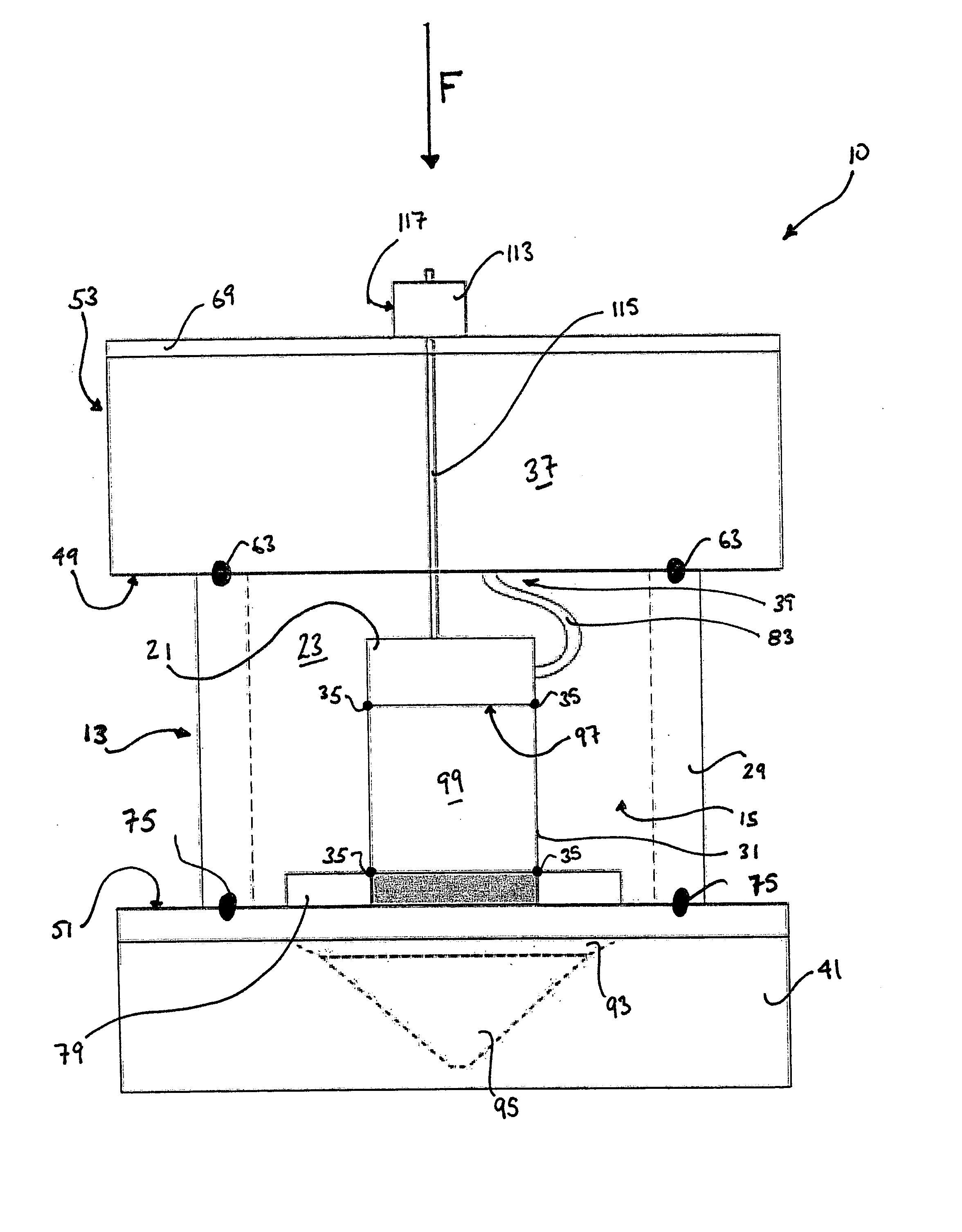
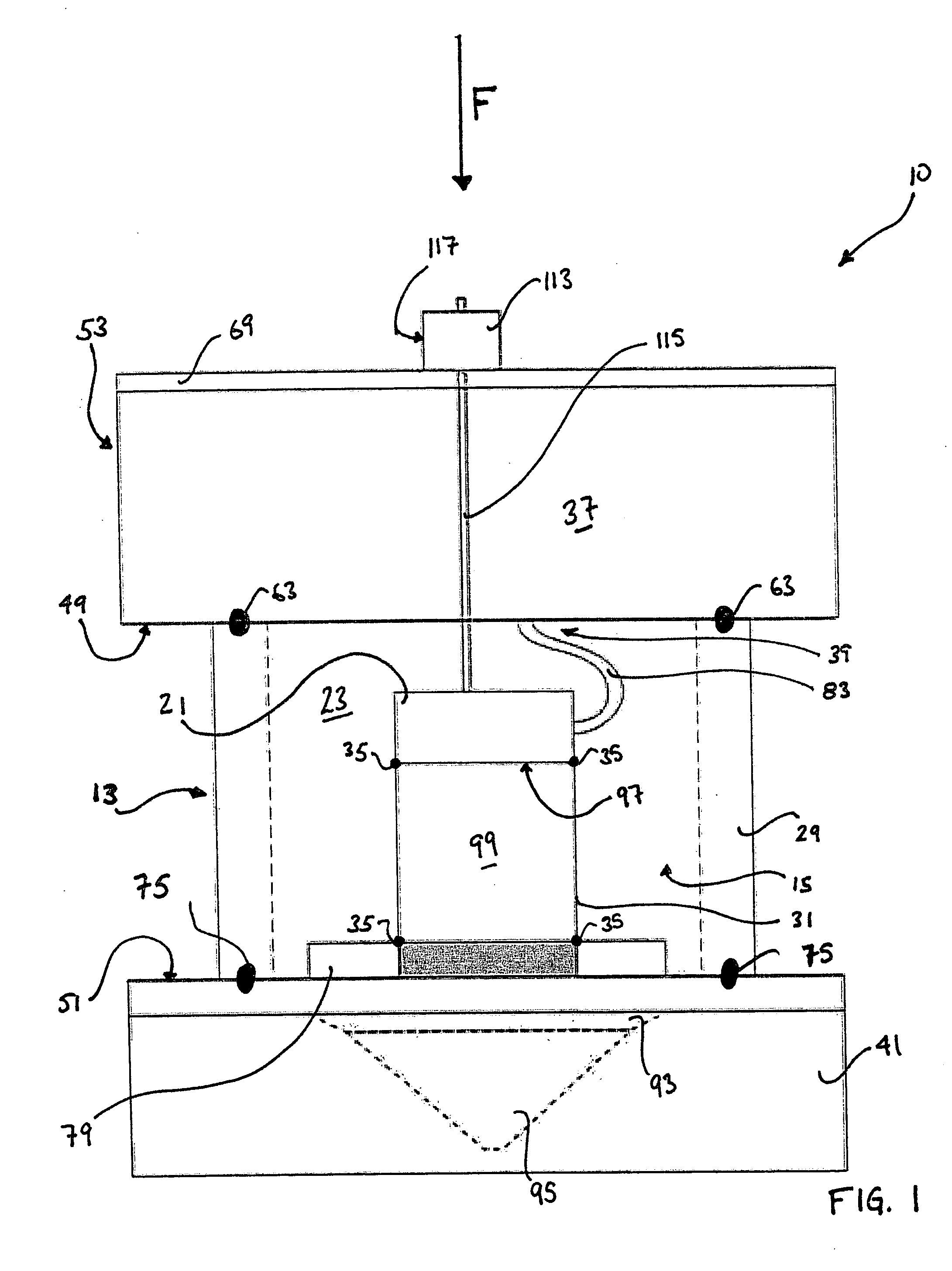
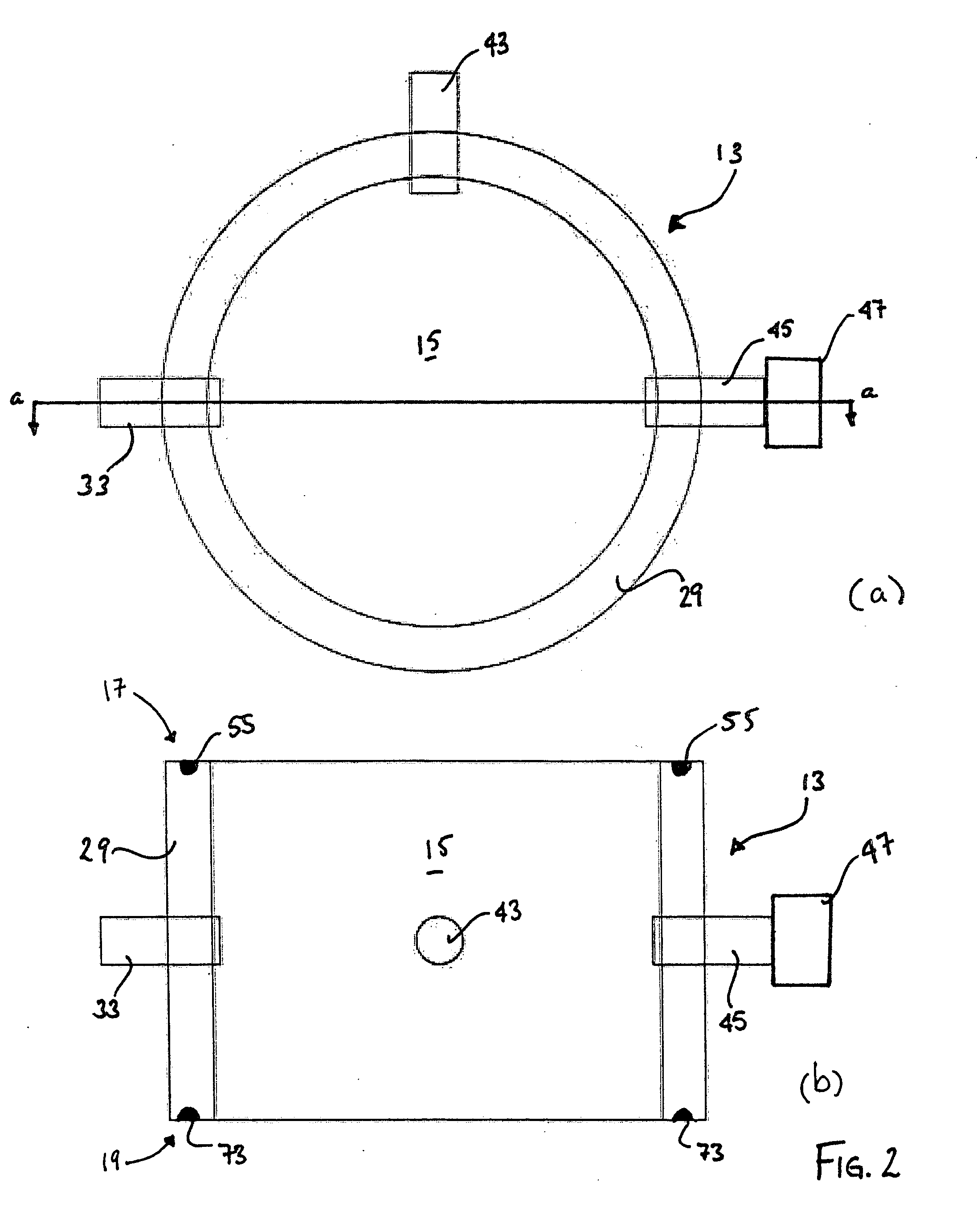
[0037] Referring to FIG. 1, a schematic cross-sectional view of a sample chamber 10 for a centrifugal permeameter for testing permeant conductivity of a porous sample 99 is illustrated. The sample chamber 10 has a confining chamber 13 having a rigid outer wall or sleeve 29 and a resilient inner sleeve 31 mountable over the sample 99. The inner sleeve 31 is positioned within the outer sleeve 29. The chamber 10 has fluid inlet means 33 for introducing a confining fluid 23 between the inner and outer sleeves (31, 29) and sealing means 35 acting between the inner and outer sleeves (31, 29) for maintaining the fluid 23 therebetween. A porous top member 21 mounts over a top face 97 of the sample 99 to supply a permeant 37 to the sample 99. The top member 21 is moveable with the sample 99 to maintain a radially outward permeant force on the sample 99 as the sample 99 is being spun in the centrifugal permeameter. A permeant supply 39 is provided for supplying the permeant 37 to the top 21; ...


PUM


Abstract

The present invention provides a sample chamber for a centrifugal permeameter for testing permeant conductivity of a porous sample, the sample chamber comprising a rigid outer sleeve; a resilient inner sleeve mountable over the sample and within the rigid outer sleeve; fluid inlet means for introducing fluid between the inner and outer sleeves; sealing means acting between the inner and outer sleeves for maintaining the fluid therebetween; a porous top member for mounting over a top face of the sample and supplying the permeant to the sample, the top being movable with the sample to maintain a radially outward permeant force on the sample as the sample is being spun in the centrifugal permeameter; a permeant supply for supplying the permeant to the porous top; and, a permeant accumulator for receiving and accumulating permeant which has passed through the sample.

Description

[0001] The present invention relates to testing and modelling the hydrodynamic properties of stress sensitive samples with a centrifugal permeameters. BACKGROUND OF THE INVENTION [0002] Prescriptive landfill legislation, guidelines and directives presently limit the hydraulic conductivity of compacted soil liners to 1×10⁻⁷ cm / S or lower. Presently sample testing liners can require between five and fourteen testing days when tested according to procedures specified by American Standard Test Method (ASTM) 5084-D. As a result of the long test times large sections of field compacted liners are not directly tested for hydraulic compliance. Present flexible wall bench testing techniques are time prohibitive and equipment intensive (samples must be transported to a laboratory for testing). Furthermore there is a lack of government and industry education. [0003] A permeameter is used to determine the fluid transport properties of a porous medium. e.g. a compacted soil layer. A current metho...

Claims


Application Information

Patent Timeline
IPC IPC(8): G01N15/08G01N33/24
CPCG01N33/24G01N15/0826G01N33/241
Inventor KNIGHT, MARK A.GILES, SHAYNE
Owner UNIVERSITY OF WATERLOO
Learn More