Kinetic energy rod warhead with lower deployment angles

a technology of kinetic energy rod and deployment angle, which is applied in the direction of weapons, ammunition projectiles, projectiles, etc., can solve the problems of not being able to reach the target, not being able being difficult to achieve the target, so as to improve the lethality, improve the lethality, and prevent casualties.

Inactive Publication Date: 2005-05-26
RAYTHEON CO
View PDF99 Cites 28 Cited by
  • Summary
  • Abstract
  • Description
  • Claims
  • Application Information

AI Technical Summary

Benefits of technology

[0020] It is a further object of this invention to provide such a kinetic energy rod warhead which has a better chance of destroying all of the bomblets and chemical submunition payloads of a target to thereby better prevent casualties.
[0021] It is a further object of this invention to provide such a kinetic energy rod warhead which improves lethality against ballistic missiles having submunition or bomblet payloads.
[0022] This invention results from the realization that a higher lethality kinetic energy rod warhead which provides for high lethality of ballistic missiles having either submunition or bomblet payloads can be achieved by including a plurality of different size projectiles that are effective against destroying both submunition and bomblet payloads.

Problems solved by technology

Moreover, biological warfare bomblets and chemical warfare submunition payloads are carried by some threats and one or more of these bomblets or chemical submunition payloads can survive and cause heavy casualties even if the “hit-to-kill” vehicle accurately strikes the target.
Blast fragmentation type warheads, unlike “hit-to-kill” vehicles, are not navigable.
The fragments, however, are not always effective at destroying the target and, again, biological bomblets and / or chemical submunition payloads survive and cause heavy casualties.
To date, however, kinetic energy rod warheads have not been widely accepted nor have they yet been deployed or fully designed.
The cylindrical shaped projectiles, however, may tend to break and / or tumble in their deployment.
Still other projectiles may approach the target at such a high oblique angle that they do not effectively penetrate the target.

Method used


Image

  • Kinetic energy rod warhead with lower deployment angles
  • Kinetic energy rod warhead with lower deployment angles
  • Kinetic energy rod warhead with lower deployment angles

Examples


Embodiment Construction

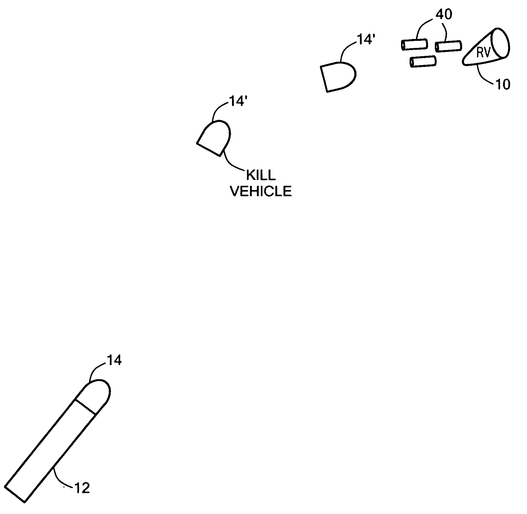
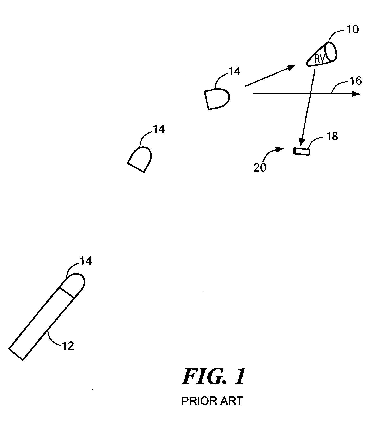
[0064] As discussed in the Background section above, “hit-to-kill” vehicles are typically launched into a position proximate a re-entry vehicle 10, FIG. 1 or other target via a missile 12. “Hit-to-kill” vehicle 14 is navigable and designed to strike re-entry vehicle 10 to render it inoperable. Countermeasures, however, can be used to avoid the kill vehicle. Vector 16 shows kill vehicle 14 missing re-entry vehicle 10. Moreover, biological bomblets and chemical submunition payloads 18 are carried by some threats and one or more of these bomblets or chemical submunition payloads 18 can survive, as shown at 20, and cause heavy casualties even if kill vehicle 14 does accurately strike target 10.

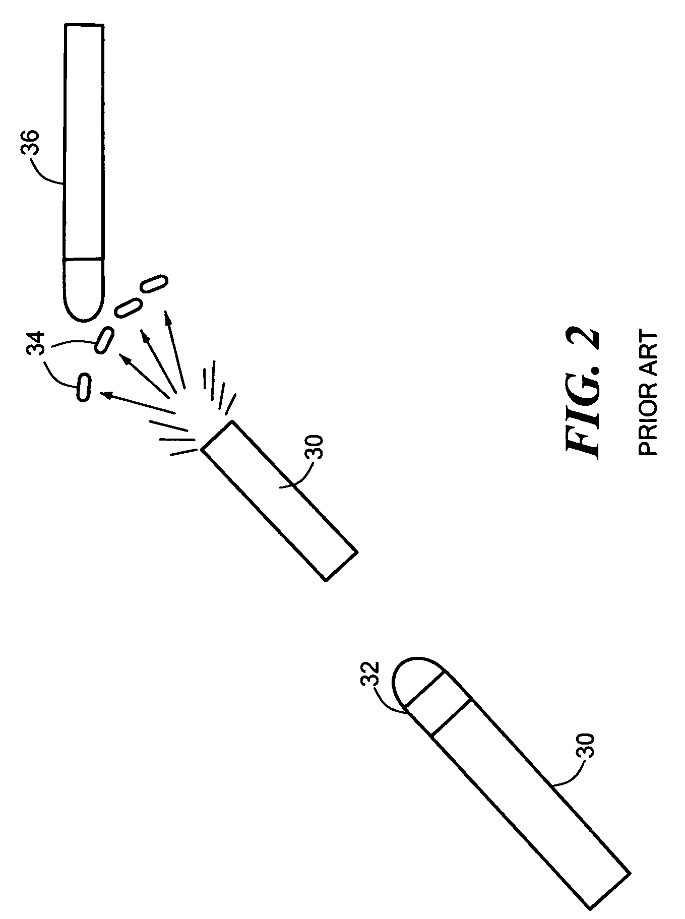
[0065] Turning to FIG. 2, blast fragmentation type warhead 32 is designed to be carried by missile 30. When the missile reaches a position close to an enemy re-entry vehicle (RV), missile, or other target 36, a pre-made band of metal or fragments on the warhead is detonated and the pieces of meta...


PUM


Abstract

This invention features a kinetic energy rod warhead including a projectile core including a plurality of different size projectiles, an explosive charge about the core, and at least one detonator for the explosive charge.

Description

RELATED APPLICATIONS [0001] This application is a Continuation-in-Part application of U.S. patent application Ser. No. 10 / 456,777, filed Jun. 6, 2003 which is a Continuation-in-Part of U.S. patent application Ser. No. 09 / 938,022 filed Aug. 23, 2001, issued on Jul. 29, 2003 as U.S. Pat. No. 6,598,534 B2.FIELD OF THE INVENTION [0002] This invention relates to improvements in kinetic energy rod warheads. BACKGROUND OF THE INVENTION [0003] Destroying missiles, aircraft, re-entry vehicles and other targets falls into three primary classifications: “hit-to-kill” vehicles, blast fragmentation warheads, and kinetic energy rod warheads. [0004]“Hit-to-kill” vehicles are typically launched into a position proximate a re-entry vehicle or other target via a missile such as the Patriot, THAAD or a standard Block IV missile. The kill vehicle is navigable and designed to strike the re-entry vehicle to render it inoperable. Countermeasures, however, can be used to avoid the “hit-to-kill” vehicle. Mo...

Claims


Application Information

Patent Timeline
Patent Type & Authority Applications(United States)
IPC IPC(8): F42B12/58
CPCF42B12/32F42B12/60F42B12/58
Inventor LLOYD, RICHARD M.
Owner RAYTHEON CO
Why Eureka
Try Eureka