Sprinkler assembly

a technology of sprinklers and assemblies, applied in mechanical equipment, transportation and packaging, valve types, etc., can solve the problems of affecting the performance of sprinklers, affecting the operation of sprinklers, etc., and achieve the effect of high performance, economical and reliabl

Inactive Publication Date: 2005-06-09
DOLAN KEVIN MICHAEL
View PDF18 Cites 134 Cited by
  • Summary
  • Abstract
  • Description
  • Claims
  • Application Information

AI Technical Summary

Benefits of technology

[0013] Accordingly, it is an object of the present invention to provide a high performance, economical and reliable sprinkler assembly for producing a controlled distribution of a fluid to a location such as a commercial structure or home dwelling.
[0014] Another object of the present invention is to provide a sprinkler assembly that may be custom built on site.

Problems solved by technology

However, in areas where the sprinkler system, in whole or in part, is subject to freezing conditions, water cannot be maintained in the sprinkler system piping since it could freeze and compromise the integrity of the system.
These regulations have placed restrictions on the use of antifreeze systems to protect against contamination of public water supplies.
All of these items have an impact on the cost effectiveness of using antifreeze systems, and thus, are disadvantageous.
The disadvantages of using a conventional dry sprinkler is that it varies in size and currently is made to order by a dry sprinkler manufacturer.
In essence, the process for installing conventional dry sprinklers is time consuming.
In addition, unlike a wet pipe system, the length of a pipe nipple in a dry sprinkler cannot be adjusted in the field by the sprinkler fitter.
If the contractor orders the wrong size or the manufacturer fabricates the wrong size, another order must be issued, which further delays the installation time.

Method used


Image

  • Sprinkler assembly
  • Sprinkler assembly
  • Sprinkler assembly

Examples


first embodiment

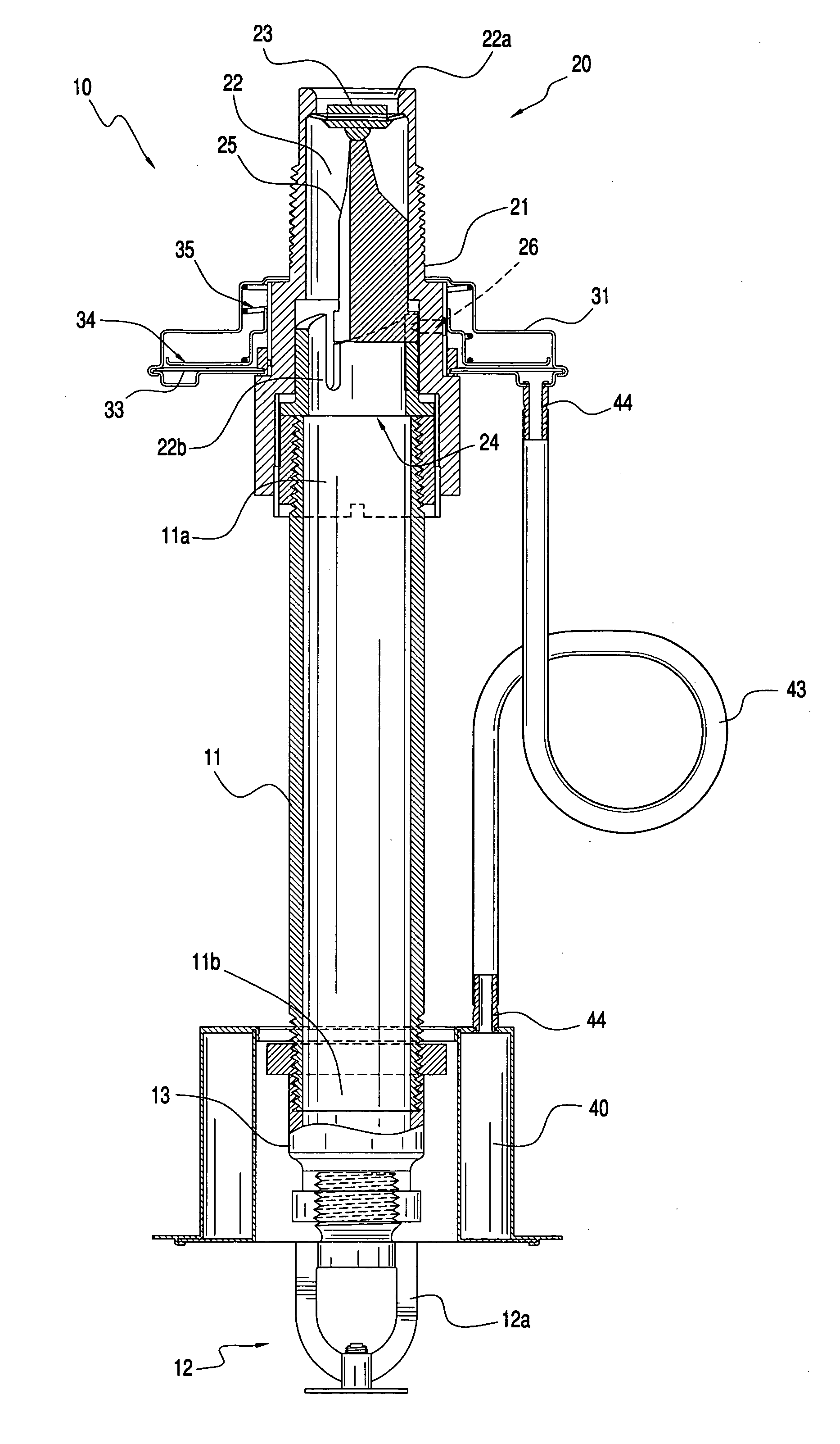
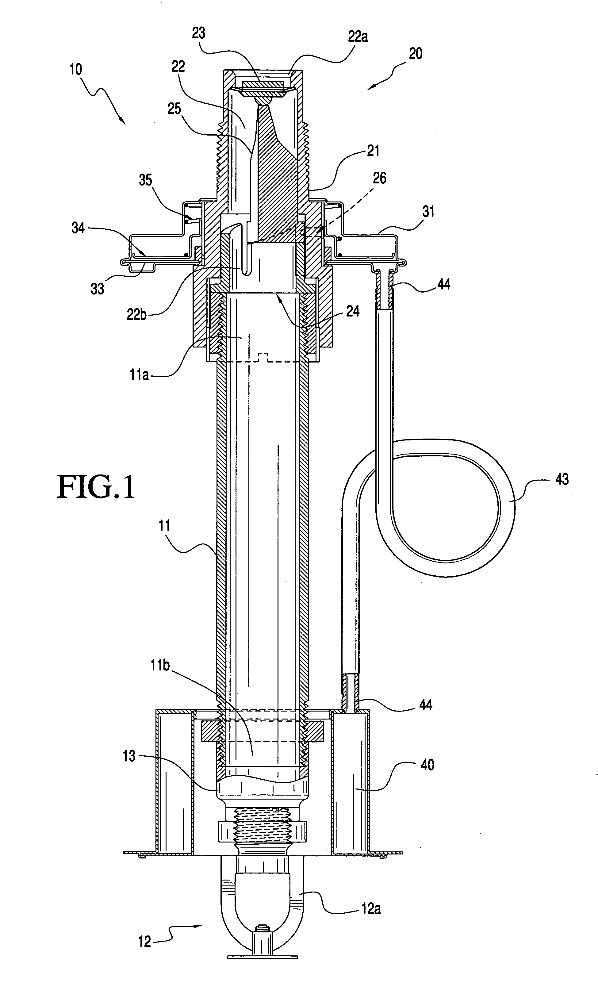
[0046] Referring now to the drawings and, more particularly, to FIG. 1, which shows in accordance with the invention a dry sprinkler assembly 10 for controlling a fire situation. The assembly 10 includes at least one fluid conduit 11, such as a length of pipe, the conduit 11 defining a flow passage including an inlet 11a for receiving a fluid from a fluid source and an outlet 11b for discharging the fluid. The assembly 10 also includes at least one dispensing mechanism 12, such as an open sprinkler head 12a which discharges a predetermined spray pattern of fluid to a selected location such as a room or space that requires protection from a fire situation.

[0047] As shown in FIG. 1, the dispensing mechanism 12, i.e., sprinkler head 12a, is connected to the conduit outlet 11b via a coupling such as a reducer 13. While a sprinkler head 12a is provided as the dispensing mechanism in accordance with the invention, it will become apparent to those skilled in the art that other mechanisms f...

second embodiment

[0066] The sprinkler head 112a includes a sprinkler head sealing mechanism for controlling fluid flow through the sprinkler head 112a and includes a seal element 112b located at the conduit outlet 111b and operable between a closed position blocking fluid flow through the sprinkler head 112a and an open position that allows fluid flow therethrough. The sprinkler head sealing mechanism also includes a sprinkler head actuator 112c for moving the seal element 112b in the open position in response to a predetermined condition, the sprinkler head actuator 112c being adapted to actuate the seal element 112b independent of the operation of the actuating mechanism (not shown). A coupling member 143 fluidically connects the sensing mechanism 140 to the actuating mechanism (not shown). While the sensing mechanism 140 of the second embodiment is axially positioned on the conduit 111 so that it is positioned adjacent the sprinkler head 112a, the coupling member 143 may have a length that permit...


PUM


Abstract

A sprinkler assembly for controlling a fire situation includes at least one fluid conduit defining a flow passage including an inlet for receiving a fluid from a fluid source and at least one outlet for discharging the fluid, and a dispensing mechanism such as an open or closed sprinkler head for distributing water to a selected location. A fluid control apparatus is provided including a valve assembly having a valve seal which is moveable between a closed position blocking fluid flow through the conduit and an open position causing fluid flow through the conduit. The fluid control apparatus further includes an actuating mechanism including a valve actuator which is operatively connected to the valve assembly for causing movement of the valve seal to the open position upon release of the sealing force. A sensing mechanism is operatively connected to the valve assembly, the sensing mechanism being thermodynamically responsive to at least one of heat, smoke, infrared radiation and ultraviolet radiation emitted by a heat source.

Description

[0001] This application is a divisional of application Ser. No. 09 / 985,039, filed Nov. 1, 2001.BACKGROUND OF THE INVENTION [0002] 1. Field of the Invention [0003] The present invention relates generally to a sprinkler assembly for controlling a fire situation. [0004] 2. Description of the Related Art [0005] Conventional methods of extinguishing chemical reactions such as fire or flames include sprinkler systems. According to the standard for the Installation of Sprinkler Systems, NFPA 13, a sprinkler system is defined as an integrated system of underground and overhead piping designed in accordance with fire protection engineering standards. The installation includes one or more automatic water supplies. The portion of the sprinkler system above ground is a plurality of specially sized or hydraulically designed piping installed in a building, structure, or area, generally overhead, and to which sprinklers are attached in a systematic pattern. The valve controlling each system riser ...

Claims


Application Information

Patent Timeline
Patent Type & Authority Applications(United States)
IPC IPC(8): A62C37/11
CPCA62C37/11Y10T137/1963
Inventor DOLAN, KEVIN MICHAEL
Owner DOLAN KEVIN MICHAEL
Why Eureka
Try Eureka