Coupling apparatus for structural members

a technology of coupling apparatus and structural members, which is applied in the direction of couplings, rod connections, manufacturing tools, etc., can solve the problems of troublesome assembling work for the construction, /i>also very troublesome, and the troublesome work for assembling the construction using the conventional coupling apparatus described above becomes more troublesom

Inactive Publication Date: 2005-06-09
SAKURA GOMME KK
View PDF13 Cites 34 Cited by
  • Summary
  • Abstract
  • Description
  • Claims
  • Application Information

AI Technical Summary

Problems solved by technology

An increase in size of a construction inevitably increases the number of structural members to be coupled with each other, which makes an assembling work for the construction being troublesome.
Moreover, in the above described conventional coupling apparatus, a work for aligning the projected end of the shaft of the bolt 14 at the one end of the tubular truss structural member 10 with the inlet of the screw hole 18a at the predetermined position on the outer peripheral surface of the node member 18 is very troublesome, and a work for rotating the collar 16 in the predetermined direction to screw the shaft of the bolt 14 into the screw hole 18a is also very troublesome.
The troublesome work for assembling a construction using the conventional coupling apparatus as described above becomes more troublesome when the above assembling work is performed in an unstable environment, such as on a body floating on water, or in underwater, aerospace, or the like.
Moreover, in the above described conventional coupling apparatus, the assembling work becomes difficult unless dimensional accuracy is strictly controlled, and the assembling work becomes furthermore difficult when elements that constitute the structural member and the coupling apparatus are exposed to external environments of high temperature and low temperature, in which the elements are thermally expanded and contractiond, for a long period.
Further, in the above environment, even after the assembling work is finished, the coupling apparatus is greatly deformed due to the thermal expansion and contraction of the elements that constitute the structural member and the coupling apparatus, thereby the coupling apparatus may be subjected to fatigue failure.

Method used


Image

  • Coupling apparatus for structural members
  • Coupling apparatus for structural members
  • Coupling apparatus for structural members

Examples


first embodiment

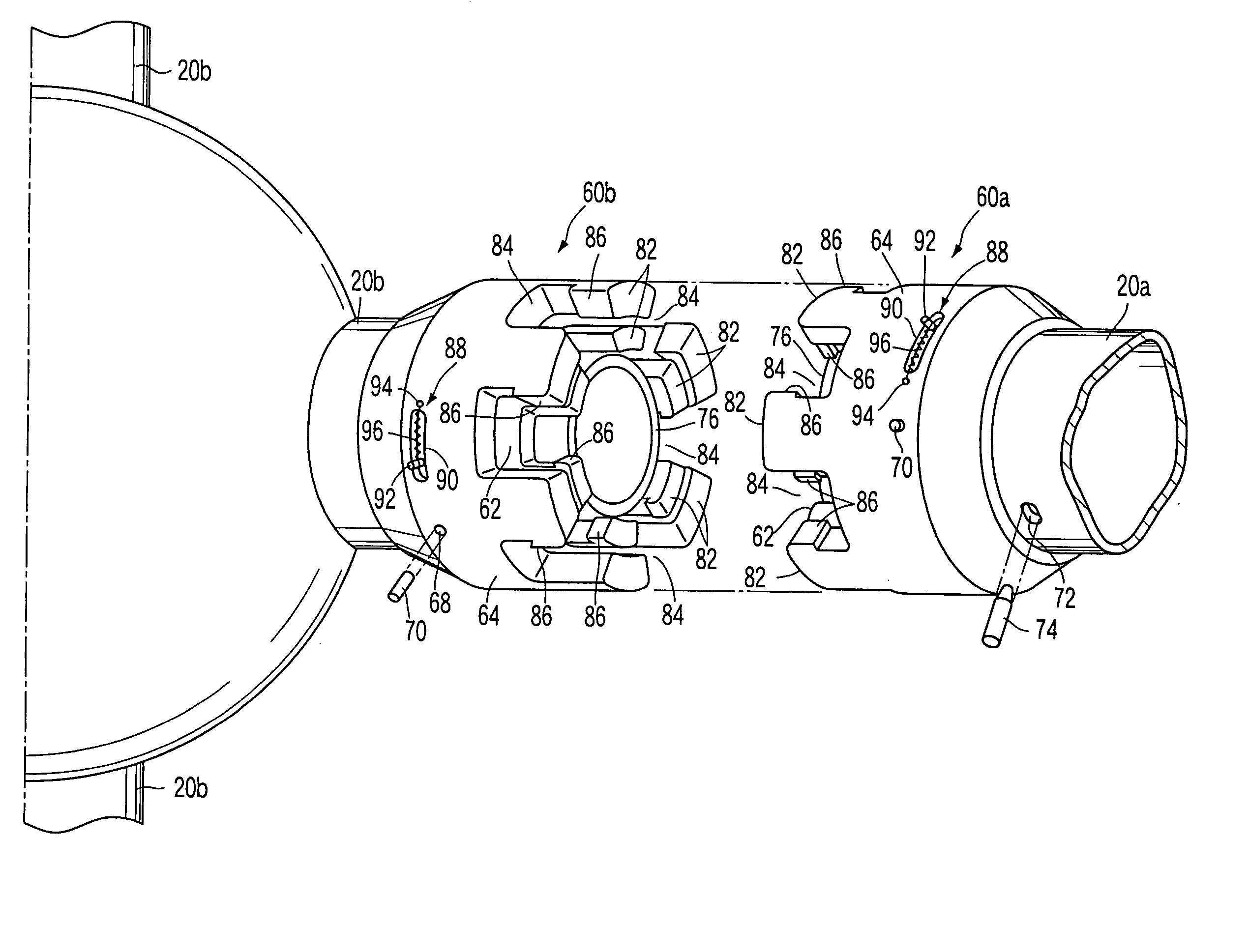
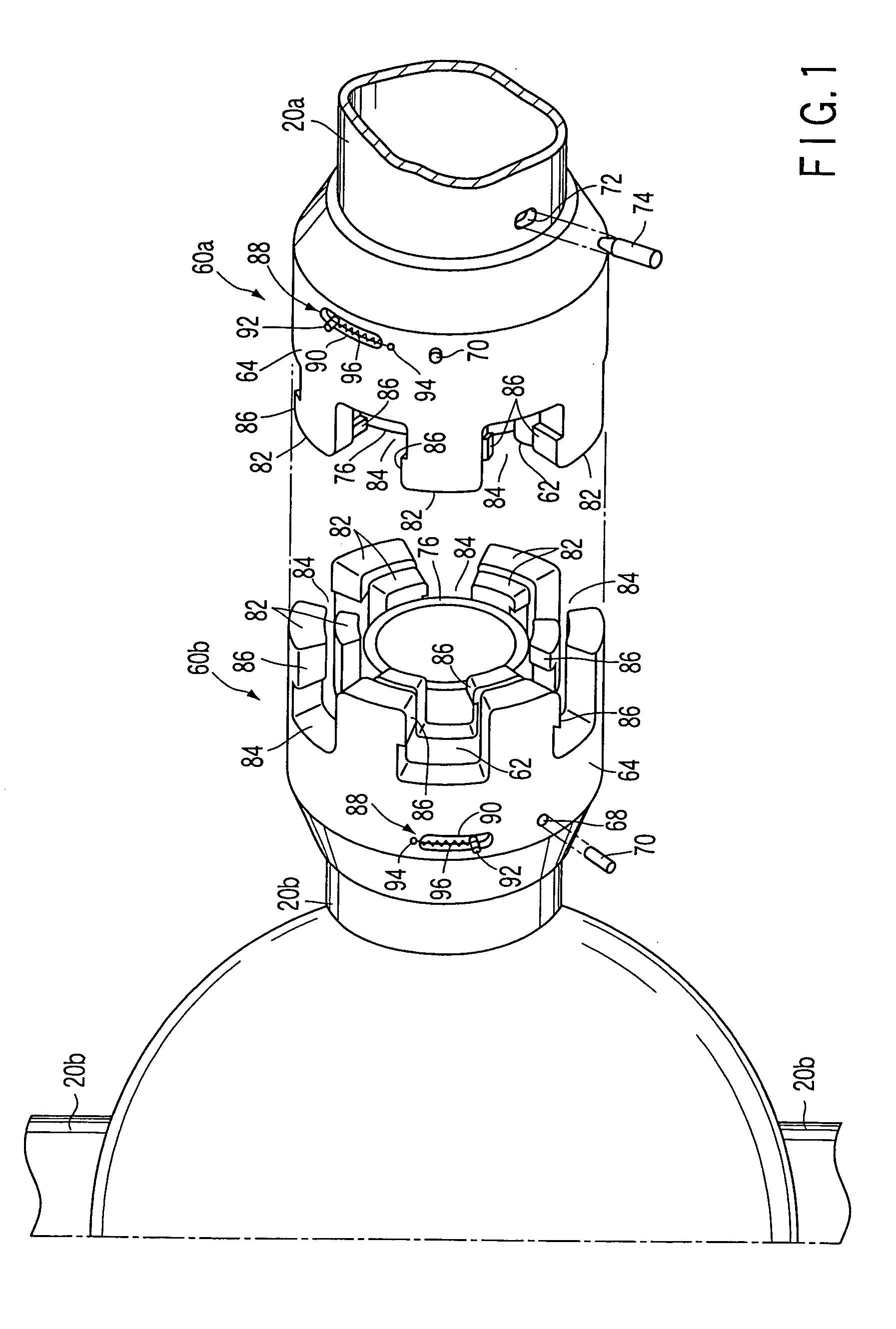
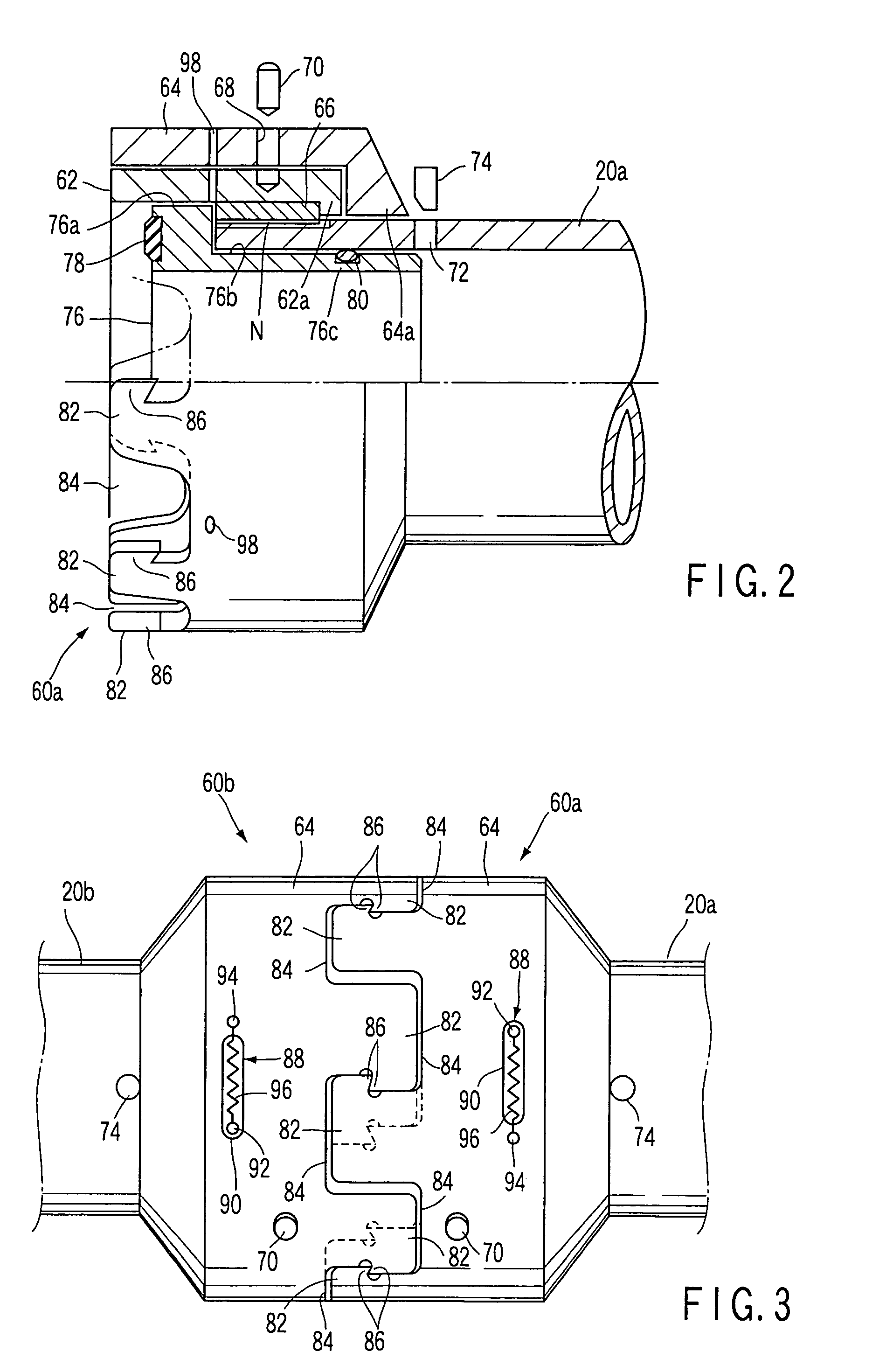
[0069] At first, a coupling apparatus for structural members according to a first embodiment of the present invention will be explained in detail with reference to FIGS. 1 to 3.

[0070] The coupling apparatus includes a pair of couplers 1040a, 60b having the same structure. Each of the pair of couplers 1040a, 60b has a double structure including a cylindrical innner coupler main body 1042 and a cylindrical outer coupler main body 1044 located on the outer peripheral surface of the inner coupler main body 1042.

[0071] The inner coupler main body 1042 is rotatably fitted into one end portion of a truss structural member 20a acting as a structural member. The inner peripheral surface of the outer coupler main body 1044 is rotatably fitted on the outer peripheral surface of the inner coupler main body 1042.

[0072] More specifically, a male screw portion N is formed on the outer peripheral surface of the one end portion of the truss structural member 20a, and a female screw portion formed...

second embodiment

[0124] A coupling apparatus of this embodiment includes a pair of couplers 100a, 100b having the same structure without male and female types. The one coupler 100a is connected to a node pipe 3 as a structural member connected to a node 2, and the other coupler 100b is connecte to a truss structural member 20a. The truss structural member 20a is connected to the node 2 by coupling the couplers 100a, 100b.

[0125] Since the couplers 100a, 100b have the same structure as to each other, the structure of one coupler 100b will be explained in the following. The coupler 100b has a double structure composed of a stopper nut 102 as an abutment member and a coupler main body 104 arranged on the outer peripheral surface of the stopper nut 102.

[0126] The stopper nut 102 is formed of a cylindrical member and is screwed on and fixed to an end portion of the truss structural member 20a. The coupler main body 104 is composed of a cylindrical member, and the inner peripheral surface thereof is rota...

third embodiment

[0148] At first, a coupling apparatus for structural members according to a third embodiment will be described in detail with reference to FIGS. 11A and 11B, and 12.

[0149] The coupling apparatus for structural members according to the third embodiment of the present invention includes a pair of couplers 22a, 22b that are mounted on the structural members 20a, 20b independent of each other and can be detachably coupled with each other to couple the structural members 20a, 20b with each other. In this embodiment, since the pair of couplers 22a, 22b have the same structure as to each other, FIGS. 11A and 11B show only one coupler 22a.

[0150] In this embodiment, the structural member 20a on which the one coupler 22a is mounted is a tubular truss structural member and formed of, for example, C20A, 20BRP (Carbon 20A, 20B iber Rein 20a, 20b orced Plastic). However, the structural member 20a may have other shape and may be formed of various materials including various metals, various resin...


PUM


Abstract

The coupling apparatus for structural members includes a paired couplers for coupling structural members with each other, and each coupler includes a cylindrical main body, engaging projections spaced apart from each other at predetermined intervals in a circumferential direction at an end of the body and projecting along the center line of the body, and engaging hooks projecting in one circumferential direction at the projecting end portions of the projections. At least one coupler further includes a coupling direction changing mechanism which couples the at least one coupler with a predetermined position of a structural member corresponding thereto so that the center line of the body of the at least one coupler can be orientated in a desired direction.

Description

CROSS-REFERENCE TO RELATED APPLICATIONS [0001] This is a Continuation Application of PCT Application No. PCT / JP03 / 05010, filed Apr. 18, 2003, which was published under PCT Article 21(2) in Japanese.[0002] This application is based upon and claims the benefit of priority from prior Japanese Patent Application No. 2002-116188, filed Apr. 18, 2002, the entire contents of which are incorporated herein by reference. BACKGROUND OF THE INVENTION [0003] 1. Field of the Invention [0004] The present invention relates to a coupling apparatus for structural members, including a pair of couplers which couples structural members independent of each other with each other. [0005] 2. Description of the Related Art [0006] It is known well to assemble a large construction by coupler a plurality of structural members independent of each other. [0007] A truss construction, for example, is well known as that construction. Conventional truss constructions are assembled by coupler a plurality of structural...

Claims


Application Information

Patent Timeline
Patent Type & Authority Applications(United States)
IPC IPC(8): F16B7/04F16D1/00
CPCF16B7/0406Y10T403/32803Y10T403/7005Y10T403/7007Y10T403/32032
Inventor NAKAMURA, TETSUYAHORIMOTO, AKIRA
Owner SAKURA GOMME KK
Why Eureka
Try Eureka