

Integrated circuit with two phase fuse material and method of using and making same
- Summary
- Abstract
- Description
- Claims
- Application Information
AI Technical Summary
Benefits of technology
Problems solved by technology
Method used
Image

Examples
Embodiment Construction
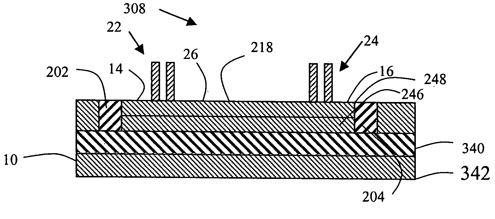
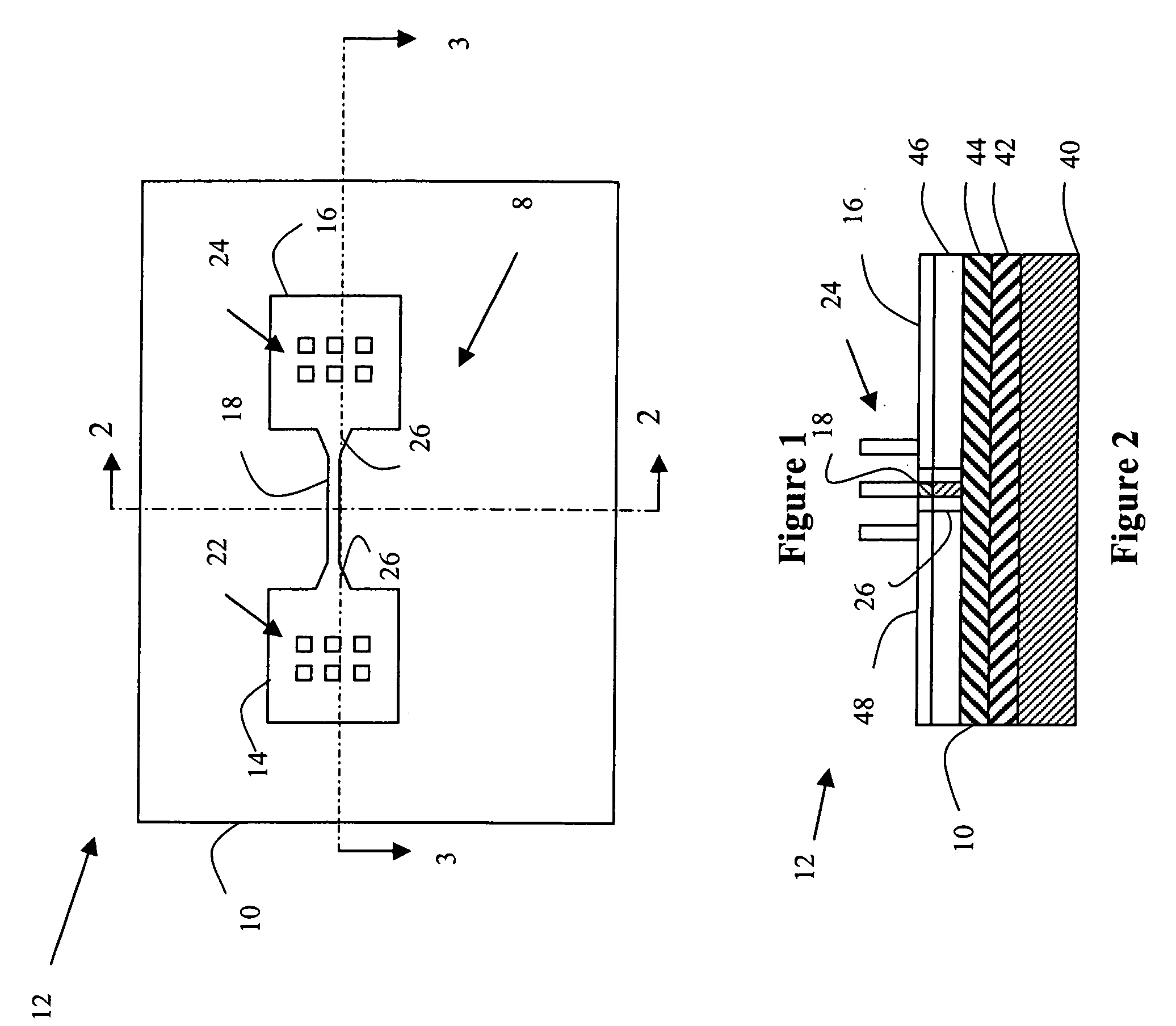
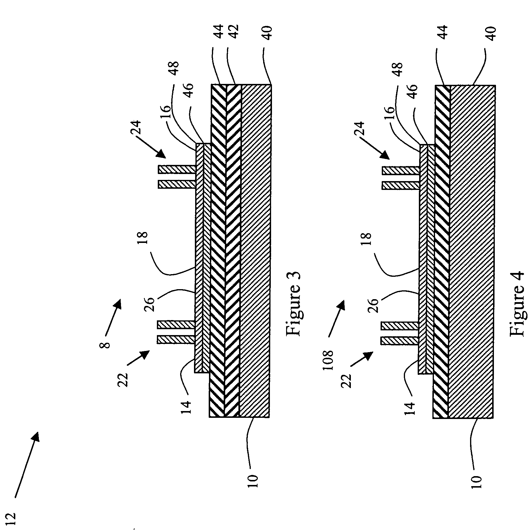
[0022] With reference to FIGS. 1-9, an exemplary embodiment of an advantageous structure and process of programming an integrated circuit (IC) fuse is described. The advantageous structure and process is preferably implemented using a material which has a first phase and a second phase. The resistivity of the material in the first phase is different than the resistivity of the material in the second phase. The material can be fabricated according to a silicidation process.
[0023] In one embodiment, the resistivity in the first phase is greater than the resistivity in the second phase. In an alternative embodiment, the fuse structure can be designed so that the material consumes a doped layer in the fuse structure to further reduce the conductivity of the fuse when programmed. The fuse can be used to drive transistors, store information, connect or disconnect circuits, etc.
[0024] With reference to FIG. 1, a portion 10 of an integrated circuit (IC) 12 includes a fuse 8. Preferably, f...
PUM
 Abstract
Description
Claims
Application Information