
Switching power supply unit and electronic apparatus having display

a technology of switching power supply and electronic equipment, which is applied in the direction of power conversion systems, dc-dc conversion, instruments, etc., can solve the problems of reducing the output voltage, and not feeding back

Active Publication Date: 2005-06-16
ROHM CO LTD
View PDF6 Cites 50 Cited by
  • Summary
  • Abstract
  • Description
  • Claims
  • Application Information

AI Technical Summary

Benefits of technology

[0008] It is therefore an object of the invention to provide a switching power supply unit having over-voltage protection functionality, characterized in that the switching power supply unit can not only protect its switching control IC against an over-voltage without any new terminal, but also, unlike conventional switching power supply units, prevent over-voltage conditions under connection failure of components.

Problems solved by technology

However, such conventional switching power supply unit has a drawback in that the feed back voltage falls to zero when the voltage detection circuit suffers an open-circuit malfunction for some reason, feeding back no voltage.
Although the output voltage is monitored, such run away of the output voltage happens because the voltage detection circuit for feedback control of the output voltage cannot detect an over-voltage caused by such open-circuit malfunction of the voltage detection circuit.
Provision of such additional terminal, however, entails a disadvantage that the switching control IC cannot be fully miniaturized.
A further disadvantage is that an over-voltage condition due to an open-circuit malfunction of a constituent element of the switching power supply unit or breaking of a wire in the unit cannot be detected by a conventional over-voltage detection circuit.

Method used


Image

  • Switching power supply unit and electronic apparatus having display
  • Switching power supply unit and electronic apparatus having display
  • Switching power supply unit and electronic apparatus having display

Examples


first embodiment

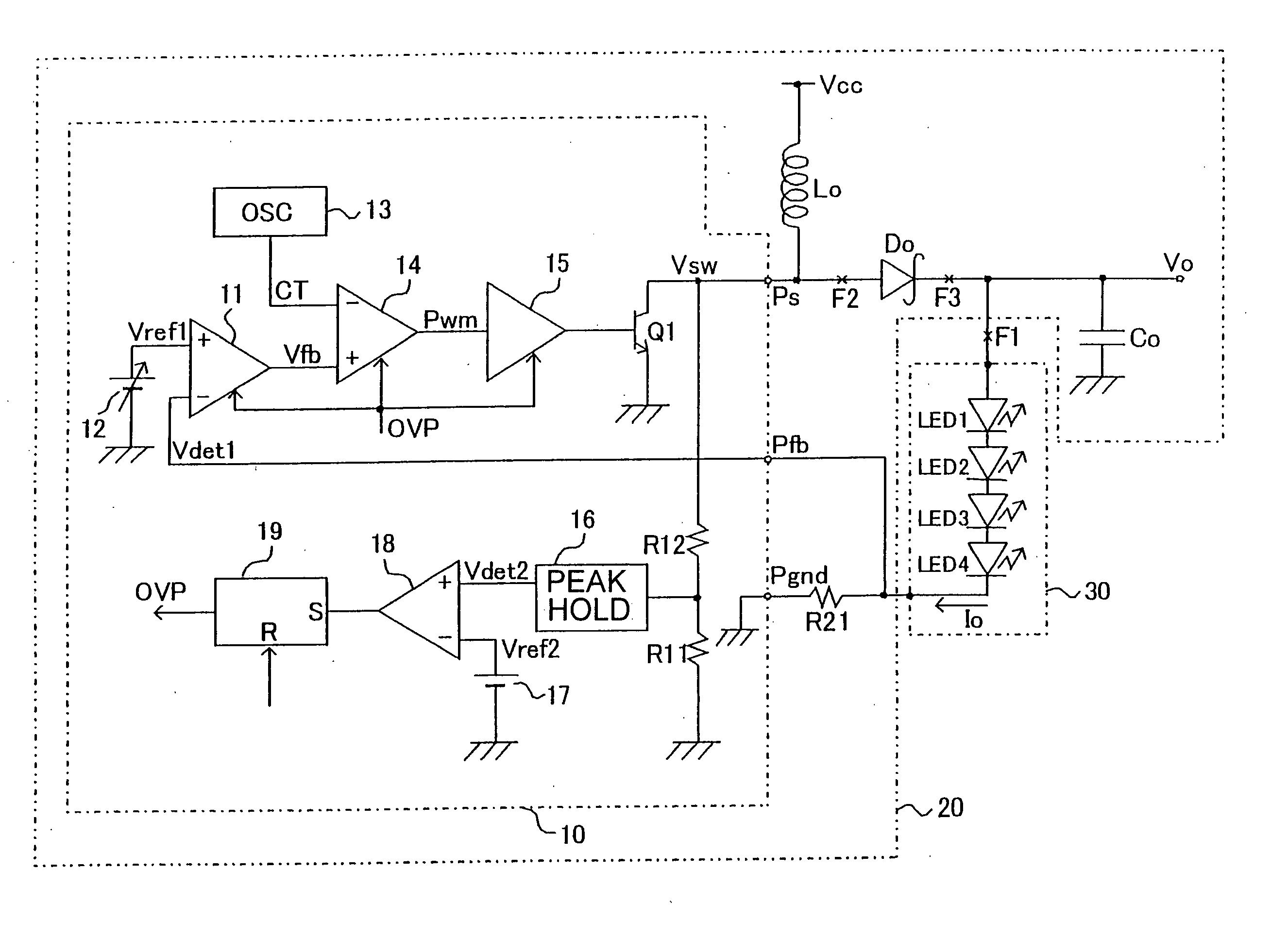
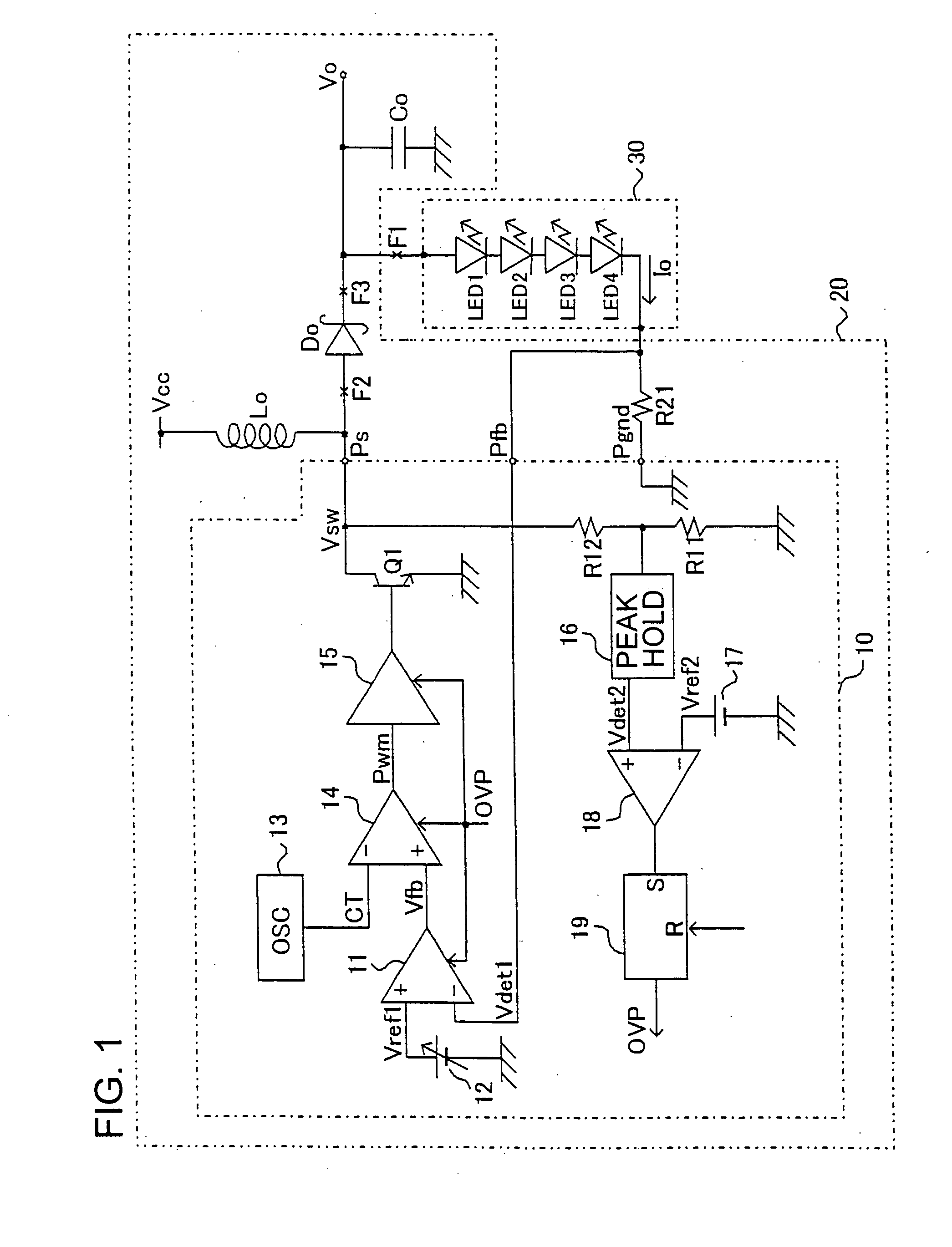
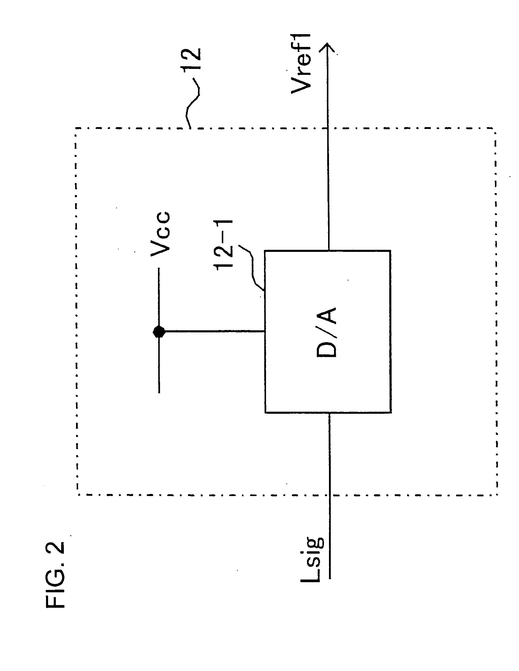
[0047] The invention will now be described in detail by way of example with reference to the accompanying drawings. Referring to FIG. 1, there is shown an electronic apparatus having a display equipped with a switching power supply unit 20 according to the invention. FIG. 2 shows the structure of an exemplary reference voltage generation circuit 12 for use in the switching power supply unit 20 of FIG. 1. FIG. 3 shows an exemplary peak hold circuit 16 for detecting an over-voltage. FIG. 4 shows a typical current-voltage characteristic of an LED constituting a load.

[0048] As shown in FIG. 1, the switching power supply unit 20 is a step-up type power supply unit configured to step-up an inputted power source voltage Vcc (which is 3.6 V for example) to a required output voltage Vo. The switching power supply unit 20 has an IC 10 for controlling the switching operation of the unit 20 (the IC referred to as switching control IC 10) for controlling the output voltage Vo. The display 30 is ...

second embodiment

[0076] Referring to FIG. 5, there is shown a switching power supply unit 20A in accordance with the invention, in which a voltage detection resistor R22 is provided in the switching IC 10A, substituting for the load of FIG. 1, i.e. display 30. The voltage detection resistor R22, together with the voltage detection resistor R21, divides the output voltage Vo to generate the first detection voltage Vdet1. The rest of the structure of the switching power supply unit 20A is the same as that of the unit 20 shown in FIG. 1.

[0077] In the inventive switching power supply unit 20A, the output voltage Vo is provided at a predetermined level in accord with the first reference voltage Vref1 set up by the first reference voltage generation circuit 12. Thus, the switching power supply unit 20A works as a constant voltage power supply unit.

[0078] Regarding open-circuit malfunctions that take place at points of malfunction, e.g. points F1 and F2, the switching power supply unit 20A of FIG. 5 provi...


PUM


Abstract

A switching power supply unit for providing an output voltage that is controlled such that a first detection voltage detected on the basis of the output voltage becomes equal to a first reference voltage. The peak voltage at the node of a serially connected coil and a switch of the switching power supply unit is detected and used as a second detection voltage for over-voltage protection. Thus, over-voltage protection of the switching power supply unit is secured with no additional terminal on the switching control IC for over-voltage protection even if such components as a feedback circuit and a rectifying diode of the power supply unit become open.

Description

FIELD OF THE INVENTION [0001] The invention relates to a switching power supply unit having an over-voltage protection function, and to an electronic apparatus having a display utilizing such power supply unit. BACKGROUND OF THE INVENTION [0002] There have been widely used switching power supply units having a coil and a switching element for stepping up an input voltage to a predetermined high output voltage. [0003] Such switching power supply unit has a voltage detection circuit for feeding back the output voltage as a feedback voltage to be compared with a reference voltage. Based on the comparison, the duty ratio and the frequency of the switching element are controlled so as to regulate the output voltage to a desired level. As a backup of the voltage control, the switching power supply unit is provided with an over-voltage protection circuit utilizing the voltage detection circuit to monitor the output voltage such that, should the detected voltage exceeds a predetermined allo...

Claims


Application Information

Patent Timeline
IPC IPC(8): H02M3/155G05F1/40H02M1/32H02M3/156
CPCH02M3/156H02M1/32H02M3/155
Inventor HOSHINO, TAICHIMATSUO, RYOUMA
Owner ROHM CO LTD
Features
  • Generate Ideas
  • Intellectual Property
  • Life Sciences
  • Materials
  • Tech Scout
  • Unparalleled Data Quality
  • Higher Quality Content
  • 60% Fewer Hallucinations
Learn More