Television tuner and method of processing a received RF signal
a television tuner and received rf technology, applied in the field of television tuners, can solve the problems of increasing overall design complexity, most significant cost in television manufacturing is the cost of the tuner, and especially serious mismatch between the two paths
- Summary
- Abstract
- Description
- Claims
- Application Information
AI Technical Summary
Problems solved by technology
Method used
Image
Examples
first embodiment
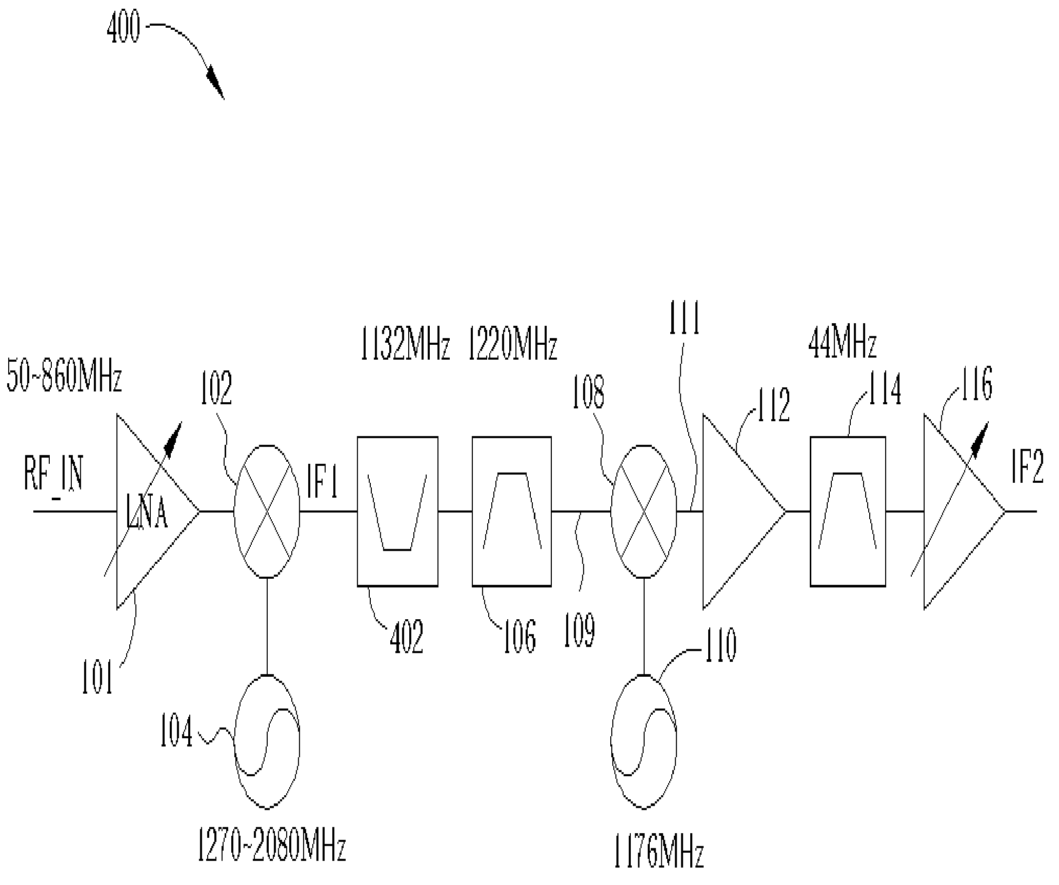
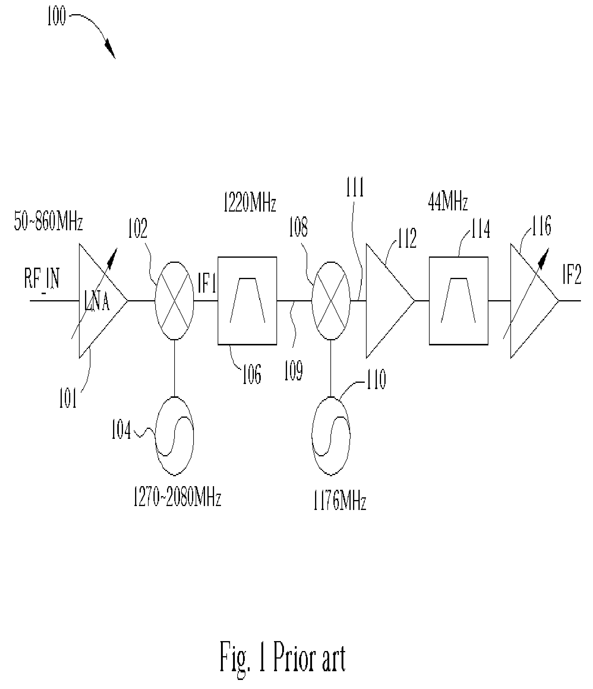
[0023]FIG. 4 shows the architecture of a television tuner 400 according to the present invention. The television tuner 400 includes the same components as the conventional television tuner 100 shown in FIG. 1 with the addition of a notch filter 402 added between the first mixer 102 and the first band-pass filter 106.
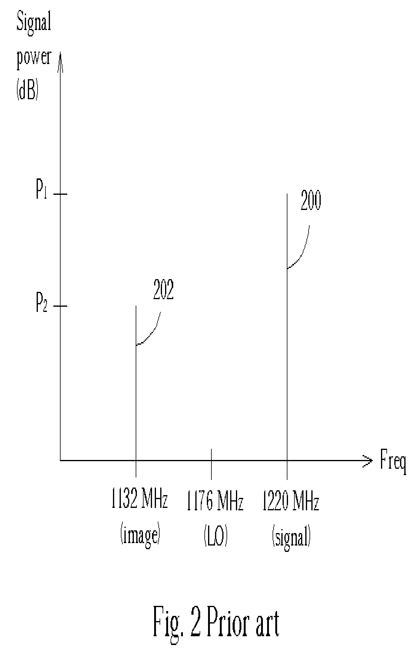
[0024] The notch filter 402 removes a first range of frequencies centered at the image frequency of 1132 MHz from the first intermediate frequency signal IF1. By using the notch filter 402, the power level P2 of the image signal 202 is further lowered. The combination of the band-pass filter 106 and the notch filter 402 allows the power difference between the image signal 202 and the desired signal 200 to be much greater than when only the band-pass filter 106 is used. In this way, the filtered intermediate frequency signal 109 output by the band-pass filter 106 easily meets the image attenuation requirement, which typically specifies that the image signal 202 be at leas...
second embodiment
[0027] Other embodiments of the present invention are also possible. FIG. 6 shows the architecture of a television tuner 600 according to the present invention. The television tuner 600 includes the adjustable low noise amplifier 101, a first harmonic mixer 602, a first local oscillator 604, the notch-filter 402, the first band-pass filter 106, a second harmonic mixer 606, a second local oscillator 608, the first intermediate frequency amplifier 112, the second band-pass filter 114, and the variable intermediate frequency amplifier 116. The operation and implementation of the harmonic mixer is explained in application Ser. No. 10 / 604018 as filed on Jun. 22, 2003, entitled “Passive Harmonic Mixer” and assigned to the same assignee, which is incorporated herein by reference. Because harmonic mixers 602, 606 are used, the first local oscillator 604 and the second local oscillator 608 run at half the frequency than those of FIG. 1 and FIG. 4. The first local oscillator 604 operates at a...
third embodiment
[0028]FIG. 7 shows the architecture of a television tuner 700 according to the present invention. The television tuner 700 includes the adjustable low noise amplifier 101, the first harmonic mixer 602, the first local oscillator 604, the notch-filter 402, the band-pass filter 106, an in-phase harmonic mixer 702, an in-phase amplifier 704, an in-phase low-pass filter 706, an in-phase variable amplifier 708, a quadrature harmonic mixer 710, a quadrature amplifier 712, a quadrature low-pass filter 714, a quadrature variable amplifier 716, and a second local oscillator 718. The second local oscillator 718 operates at a fixed frequency of 610 MHz and provides a 0° phase-delayed signal, a 45° phase-delayed signal, a 90° phase-delayed signal, and a 135° phase-delayed signal. The output of the television tuner 700 is an in-phase baseband signal I and a quadrature baseband signal Q. The full operation and benefits of the harmonic architecture television tuner are further explained in applica...
PUM
 Abstract
Description
Claims
Application Information
 - R&D
- Intellectual Property
- Life Sciences
- Materials
- Tech Scout
- Unparalleled Data Quality
- Higher Quality Content
- 60% Fewer Hallucinations
Browse by: Latest US Patents, China's latest patents, Technical Efficacy Thesaurus, Application Domain, Technology Topic, Popular Technical Reports.
© 2025 PatSnap. All rights reserved.Legal|Privacy policy|Modern Slavery Act Transparency Statement|Sitemap|About US| Contact US: help@patsnap.com


