Up/down conversion circuitry for radio transceiver

a conversion circuit and radio transceiver technology, applied in the field of circuitry for radio transceivers, can solve the problems of unsatisfactory signals, limited if and limited use of new architectures using double-quadrature mixer topology

Active Publication Date: 2007-03-20
ZARBANA DIGITAL FUND
View PDF10 Cites 81 Cited by
  • Summary
  • Abstract
  • Description
  • Claims
  • Application Information

AI Technical Summary

Benefits of technology

[0012]Also in accordance with the invention there is provided a method for down converting, in two stages, a received RF information signal to a base band information signal wherein a first stage converts the RF information signal to an IF information signal and a second the stage converts the IF information signal to the base band information signal. The RF information signal is down converted to the IF information signal using an RF oscillator signal. The IF information signal is down converted to the base band signal using image rejection down conversion means for achieving substantial image signal rejection and an IF oscillator signal. Each of the RF and IF oscillator signals is generated whereby the IF oscillator signal is an integer (N) sub-harmonic of the RF oscillator signal, including preselecting the frequency value of the IF oscillator signal to be within the operating frequency band of the image rejection down conversion means. The method may be applied for use in a multiple channel radio transceiver whereby the RF and IF oscillator signals are generated for each channel of the multiple channels and each of the IF oscillator signals has a different frequency from one channel to another.

Problems solved by technology

At each down conversion stage of the receiver, this results in the presence of undesired signals in the image band for a desired information signal and these undesired signals must be excluded.
As for the traditional architecture, this new architecture which makes use of a double-quadrature mixer topology is also limited to a relatively low IF because the known double-quadrature mixers are non-operative at high RF frequencies.

Method used


Image

  • Up/down conversion circuitry for radio transceiver
  • Up/down conversion circuitry for radio transceiver
  • Up/down conversion circuitry for radio transceiver

Examples


Embodiment Construction

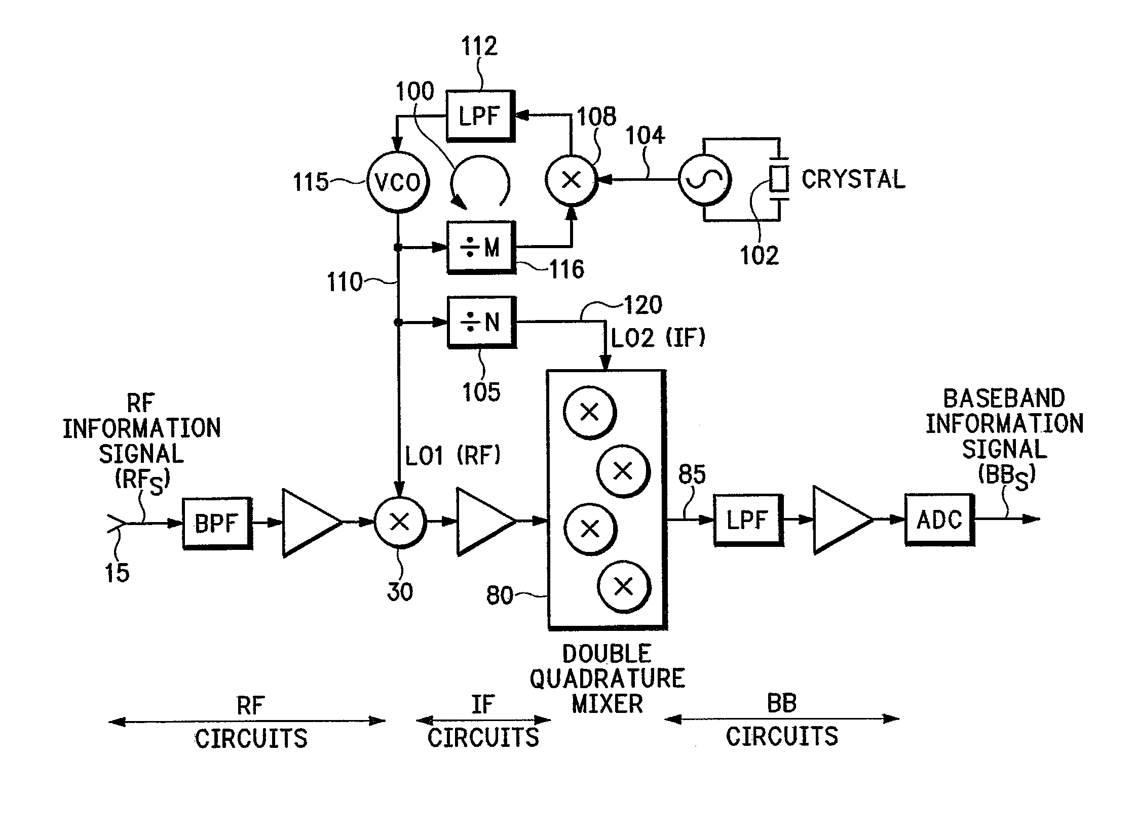
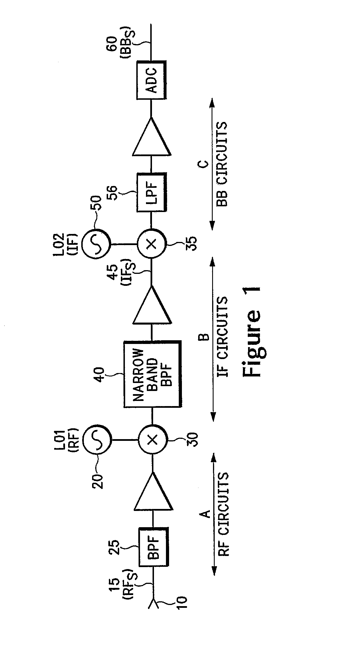
[0021]A circuit architecture for the traditional prior art heterodyne receiver is shown in FIG. 1 in which a local oscillator LO120, providing an RF oscillator signal, is used for a first down conversion of an RF band information signal (RFs) to an IF band signal using a mixer component 30, a second local oscillator LO250, providing an IF oscillator signal, is used for a second down conversion of the IF band information signal (IFs) 45 to base band using a mixer 35 and a narrow band filter (BPF) 40 is provided to extract the IFs signal 45 at the IF stage prior to the second down conversion. For a multi-carrier application, such as an embodiment implementing the 802.11a 5 GHz wireless standard, the local oscillator LO120, providing the RF oscillator signal, must be tunable to multiple RF carrier frequencies.

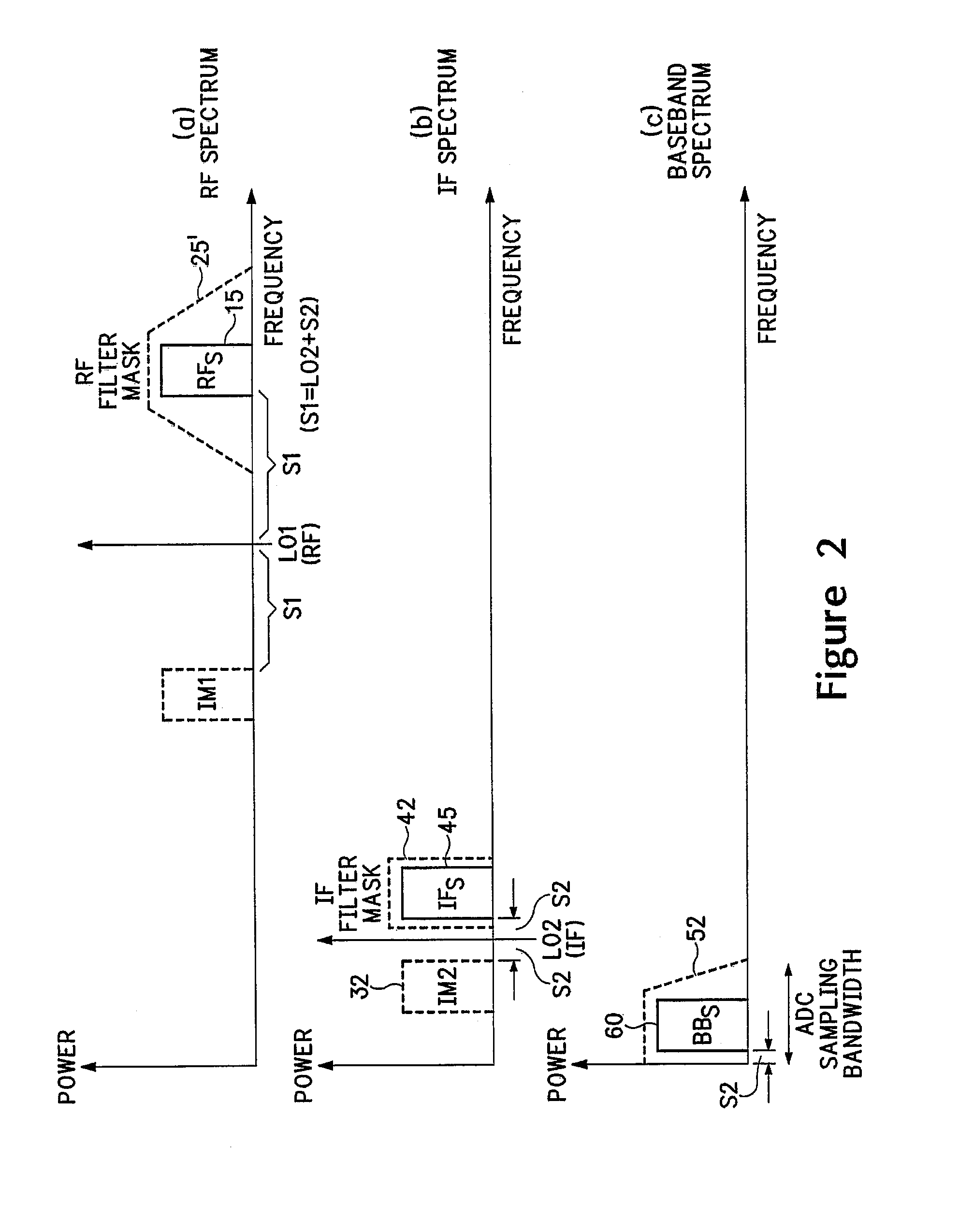
[0022]FIG. 2(a) illustrates portions of the frequency spectrum occupied by an exemplary RF signal received at a multi-channel receiver antenna 10 and FIGS. 2(b) and (c) illustrate...


PUM


Abstract

A multi-channel RF receiver uses an image rejection mixer (e.g. double quadrature mixer) in the IF down conversion stage for image side band rejection (whereby use of an IF narrow band filter for image rejection may be omitted if desired) and comprises a simplified frequency synthesizer which generates both a “wandering” IF oscillator frequency and an RF oscillator frequency for the up / down conversion stages (being, for down conversion, from RF to IF and from IF to base band. The IF used for a particular RF carrier (channel) is selected so as to be both an integer (N) sub-harmonic of that RF carrier and within the operating frequency band of the image rejection mixer. Advantageously, the synthesizer comprises only one loop and one VCO, wherein the IF oscillator signal is produced from the RF oscillator signal by means of a frequency divider.

Description

FIELD OF THE INVENTION[0001]The invention relates to circuitry for a radio transceiver and in particular to up and down conversion circuitry which uses a single frequency synthesizer for both the RF (radio frequency) and IF (intermediate frequency) stages of frequency up and down conversion.BACKGROUND[0002]In the transmitter portion of a transceiver used for communicating digital data, a baseband information signal is typically scrambled, encoded, and interleaved before being modulated and then up-converted to a radio frequency, and amplified, for radio (wireless) transmission. The receiver portion of the transceiver performs the reverse processes including down-converting a received RF signal to baseband.[0003]As is well known by persons skilled in the art, in a traditional heterodyne receiver the up and down conversion from baseband to RF and from RF to baseband, respectively, is done in two stages to introduce an intermediary frequency (IF). In the up conversion process (converti...

Claims


Application Information

Patent Timeline
Patent Type & Authority Patents(United States)
IPC IPC(8): H04L27/16H03D7/16H04B1/26H04B1/30
CPCH03D7/163H04B1/30H04B1/26
Inventor BIRKETT, ALEXANDER NEILWIGHT, JAMES STUART
Owner ZARBANA DIGITAL FUND
Why Eureka
Try Eureka