Sampling system

a sampling system and sampling technology, applied in the field of sampling systems, can solve the problems of large power consumption, difficult circuit size reduction, and complicated circuits

Inactive Publication Date: 2001-01-30
KK TOSHIBA
View PDF16 Cites 83 Cited by
  • Summary
  • Abstract
  • Description
  • Claims
  • Application Information

AI Technical Summary

Problems solved by technology

Here, it is very difficult to reduce the size of the circuit because the mixers 14 and 17 are composed of analog devices in general.
Although mixer circuits which are suitable for the miniaturization of the circuit have been proposed and put into the practical use so far, all of them have had a problem that the power consumption is large or the circuit is complicated because they are intended to attain an enough dynamic range and performances such as low distortion characteristics.
Because an IF filter needs to be composed of passive parts such as a ceramic filter in many cases to enhance the frequency selectivity, the size of the filter becomes large and it is not suited for the use of the radio receiving device of portable equipment which are required to be miniaturized.
Although the structure of the whole system may be miniaturized because no mixer nor IF filter are necessary in the down-sampling system shown in FIG. 2, there has been a problem that the band-pass filter 23 is required to have a high frequency selectivity and the size of the filter becomes also large because the noise signal (hereinafter referred to as aliasing noise) aliased due to the sampling in the A / D converter 24 needs to be removed by the band-pass filter 23.
As described above, the radio receiving device of the prior art double super-heterodyne system has had the problems that (1) because the mixer is required to have the wide dynamic range and the low distortion characteristic, the mixer requires the large quantity of power consumption and complicates the circuit structure and (2) the IF filter (e.g. the ceramic filter) having the high frequency selectivity is required to select the frequency signal of the received channel and to remove the signal of the image frequency, increasing the dimension of the filter required here.
The radio receiving device of the system of down-sampling the modulated signal directly by the A / D converter has had the problems that the dimension of the filter increases and the noise figure becomes worse due to the high down-sampling ratio, i.e. the generated noise increases, because the filter having the high frequency selectivity such as the ceramic filter or a dielectric filter is required in the radio frequency signal processing section in order to remove the aliasing noise generated during the down-sampling.

Method used


Image

  • Sampling system
  • Sampling system
  • Sampling system

Examples


first embodiment

[First Embodiment]

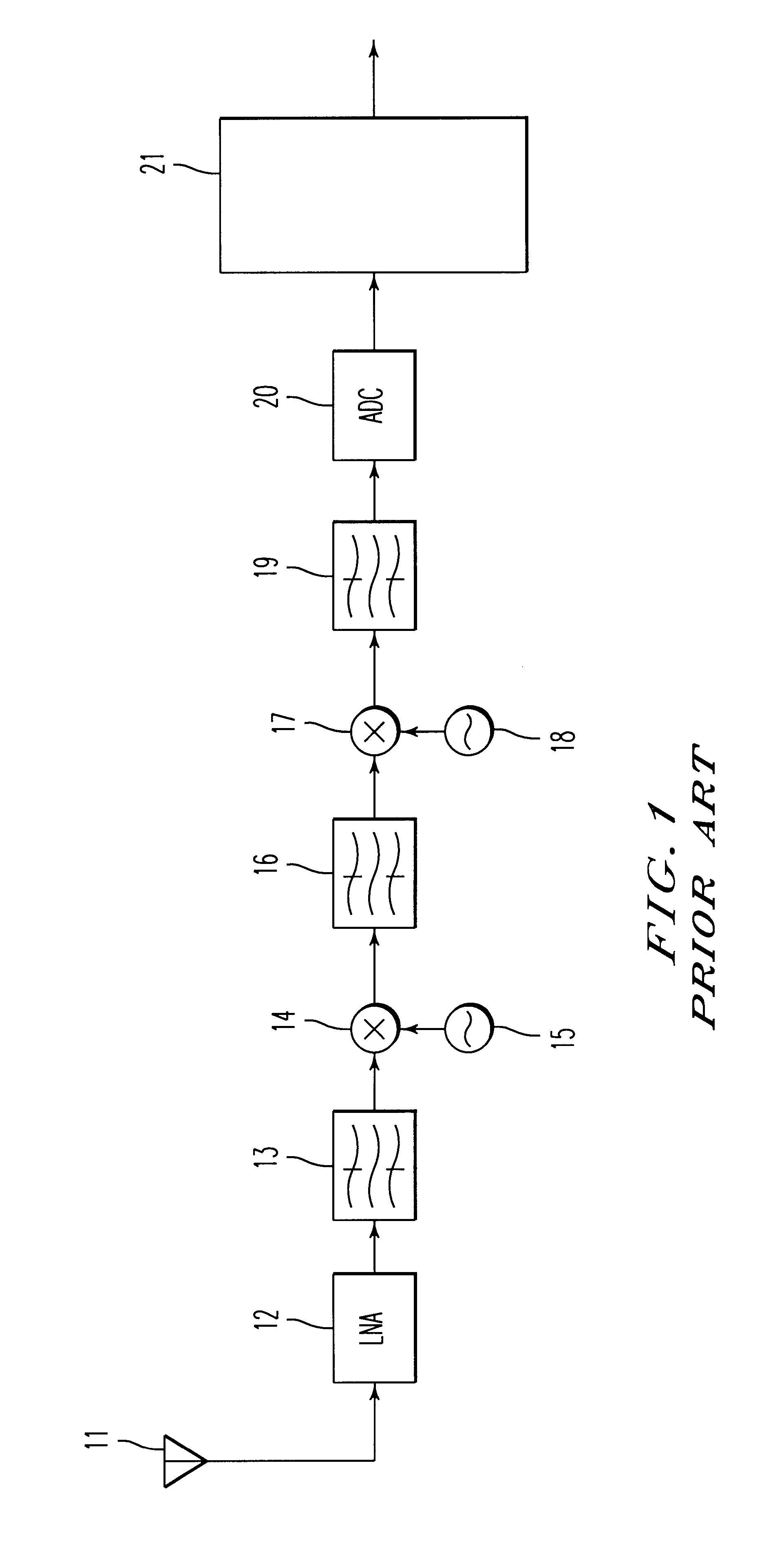
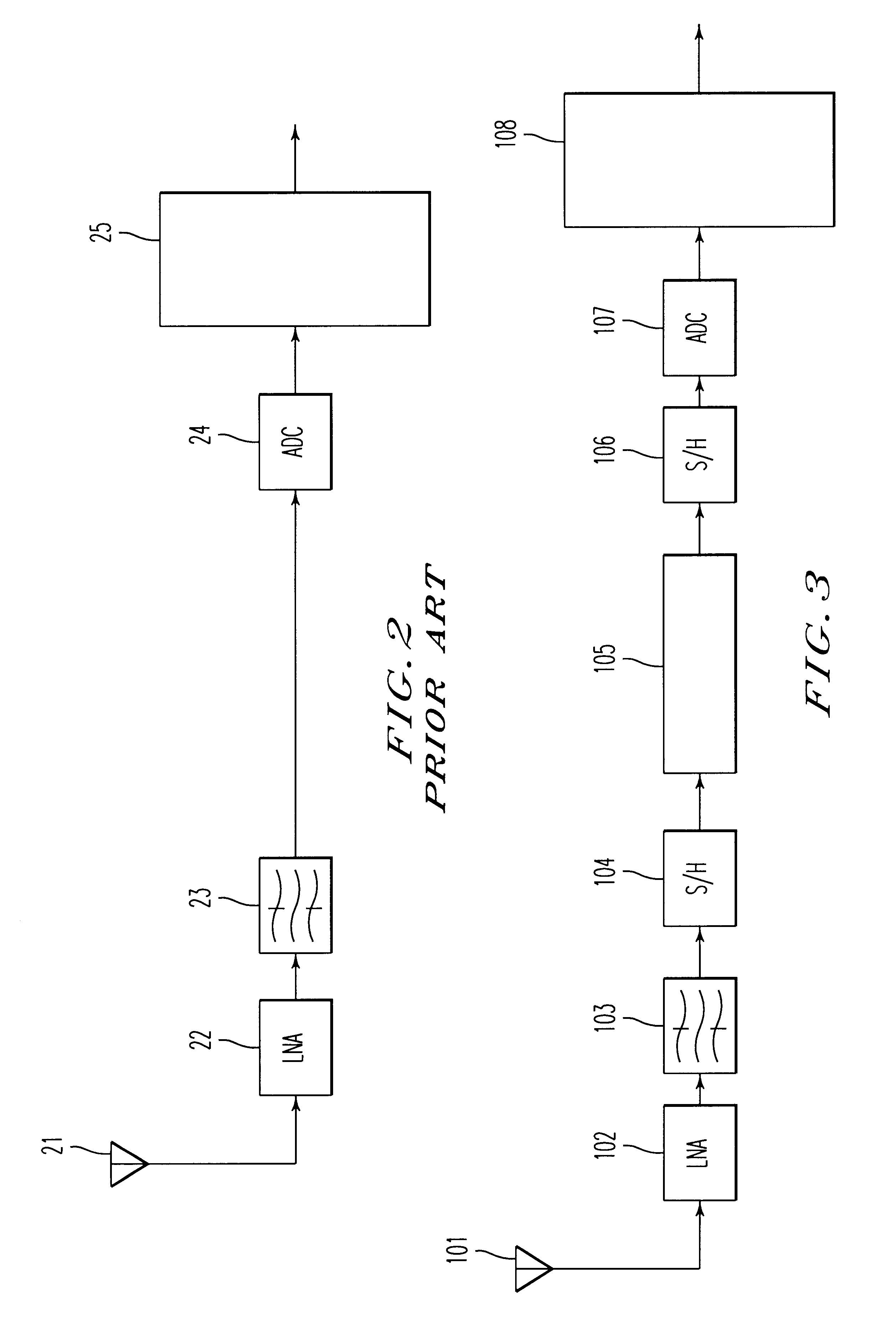
FIG. 3 is a block diagram showing the structure of a radio receiving device using a sampling system of a first embodiment of the present invention. A modulated signal received by an antenna 101 is amplified by a low noise amplifier (LNA) 102 and is then input to a band-pass filter 103 having a relatively moderate characteristic for suppressing an image signal.

The signal output from the band-pass filter 103 is over-sampled by a first sample and hold circuit 104. That is, the sampling frequency fs1 of the first sample and hold circuit 104 is set at a frequency higher than the signal band fb of the modulated signal, or more concretely, at a frequency higher than the signal band fb by twice or more. The first sample and hold circuit 104 oversamples with respect to the input signal band.

When the sampling frequency of the first sample and hold circuit 104 is set with respect to the carrier frequency fin of the modulated signal at fs1=fin / N, the modulated signal is freque...

second embodiment

[Second Embodiment]

FIG. 4 is a block diagram showing the structure of a radio receiving device using a sampling system of a second embodiment of the present invention. The present embodiment is arranged such that the part of the first sample and hold circuit 104 and the analog decimation filter 105 in FIG. 3 is replaced by a first sample and hold circuit 200 having a filtering function.

A modulated signal received by the antenna 101 is amplified by the low noise amplifier (LNA) 102 and is then input to the band-pass filter 103 having a relatively moderate characteristic for suppressing an image signal.

The signal output from the band-pass filter 103 is input to the sample and hold circuit 200 having the first filtering function to be sampled with the sampling frequency fs1 which is higher than the signal band of the modulated signal, similarly to the first embodiment. In the sample and hold circuit 200 having the first filtering function, the input signal is input sequentially to a pl...

third embodiment

[Third Embodiment]

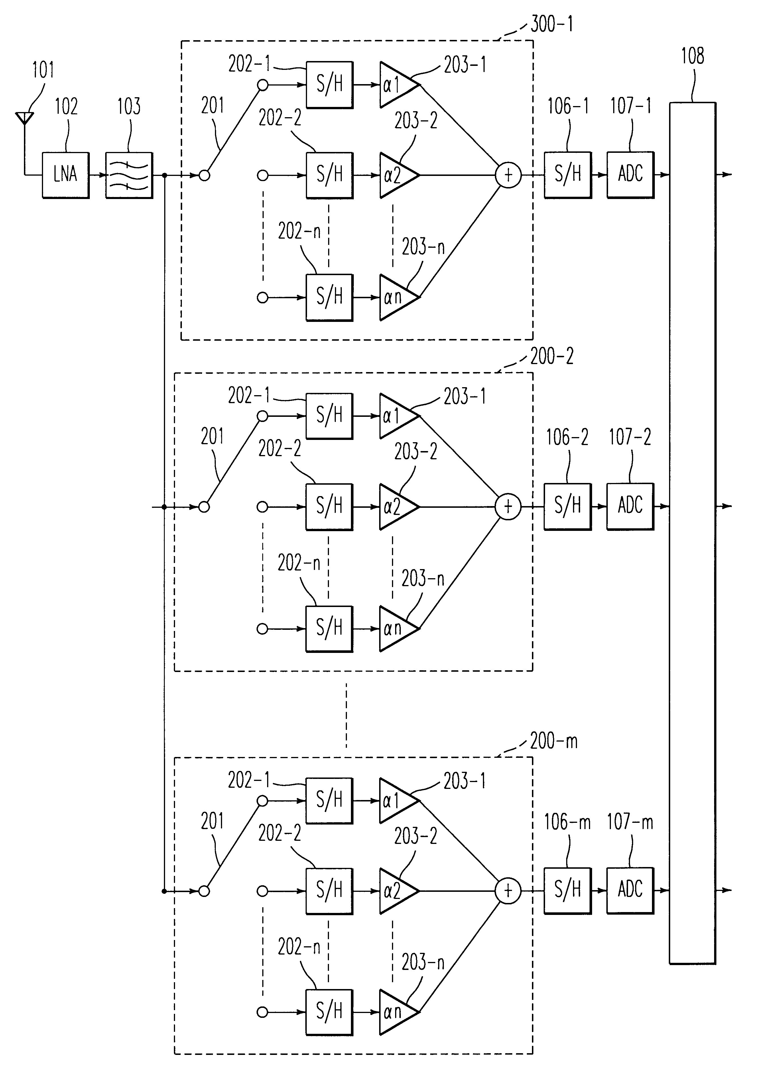
FIG. 5 is a block diagram showing the structure of a radio receiving device using a sampling system of a third embodiment of the present invention. The present embodiment is arranged such that the part of the first sample and hold circuit 104, the analog decimation filter 105 and the second sample and hold circuit 106 in FIG. 3 are replaced by a sample and hold circuit 300 having the first and second sample and hold circuit which functions also as a filter in FIG. 5. FIG. 6 is a timing chart for explaining the operation of the radio receiving device shown in FIG. 5.

In FIG. 5, a modulated signal received by the antenna 101 is amplified by the low noise amplifier (LNA) 102 and is then input to the band-pass filter 103 having a relatively moderate characteristic for suppressing an image signal. The signal output from the band-pass filter 103 is input to the first and second sample and hold circuit 300 which functions also as a filter. The sample and hold circuit 300 h...


PUM


Abstract

A sampling system arranged such that a modulated signal received by an antenna and input via a low noise amplifier and a band-pass filter is sampled at a sampling frequency higher than the signal band of the modulated signal by a first sample and hold circuit and is input to an analog decimation filter to remove a frequency component which may turn out to be aliasing noise. The output of the analog decimation filter is sampled with a sampling frequency lower than the sampling frequency of the first sample and hold circuit by a second sample and hold circuit and is digitized by an A / D converter to be demodulated by a demodulator. The sampling system which can convert the modulated signal into a low frequency without using the highly precision mixer circuit or a filter having sharp characteristics may be provided by constructing as described above.

Description

1. Field of the InventionThe present invention relates to a sampling system suited for frequency-converting a modulated signal into a low frequency and a radio receiving device using the sampling system.2. Description of Related ArtFIG. 1 shows the typical structure of a receiving device of a portable telephone and other mobile communication radio equipment. It is a radio receiving device of a double super-heterodyne system, wherein a modulated signal received by an antenna 11 is amplified by a low noise amplifier (LNA) 12 and is then input to a band-pass filter 13 having a relatively moderate characteristic for suppressing an image signal. The signal output from the band-pass filter 13 is frequency-converted in a first mixer 14 by a local signal from a local oscillator 15 into a signal having a first intermediary frequency. The signal frequency-converted by the first mixer 14 is input to a second mixer 17 via an IF filter 16 to be frequency-converted into a signal having a second i...

Claims


Application Information

Patent Timeline
Patent Type & Authority Patents(United States)
IPC IPC(8): H03D3/00H03M3/00H04B1/26H03H15/00H03H19/00
CPCH03D3/006H03M3/344H03M3/47
Inventor YASUDA, AKIRA
Owner KK TOSHIBA
Why Eureka
Try Eureka