Antenna impedance matching device and method for a portable radio telephone

a portable radio telephone and antenna impedance matching technology, applied in the field of portable radio telephone antenna impedance matching devices, can solve the problems of not being able to match the antenna impedance optimally, the above device for matching an antenna impedance, and the related antenna impedance matching ar

Inactive Publication Date: 2005-06-16
LG ELECTRONICS INC
View PDF7 Cites 129 Cited by
  • Summary
  • Abstract
  • Description
  • Claims
  • Application Information

AI Technical Summary

Problems solved by technology

However, the foregoing device for matching an antenna impedance has the following problem.
Second, the antenna impedance matching in the related art cannot match the antenna impedance optimally for both when the antenna is extracted and when it is retracted.
Third, the antenna impedance matching in the related art only by sensing the casing state cannot match the antenna impedance optimally for both a reception and a transmission mode.

Method used


Image

  • Antenna impedance matching device and method for a portable radio telephone
  • Antenna impedance matching device and method for a portable radio telephone
  • Antenna impedance matching device and method for a portable radio telephone

Examples


first embodiment

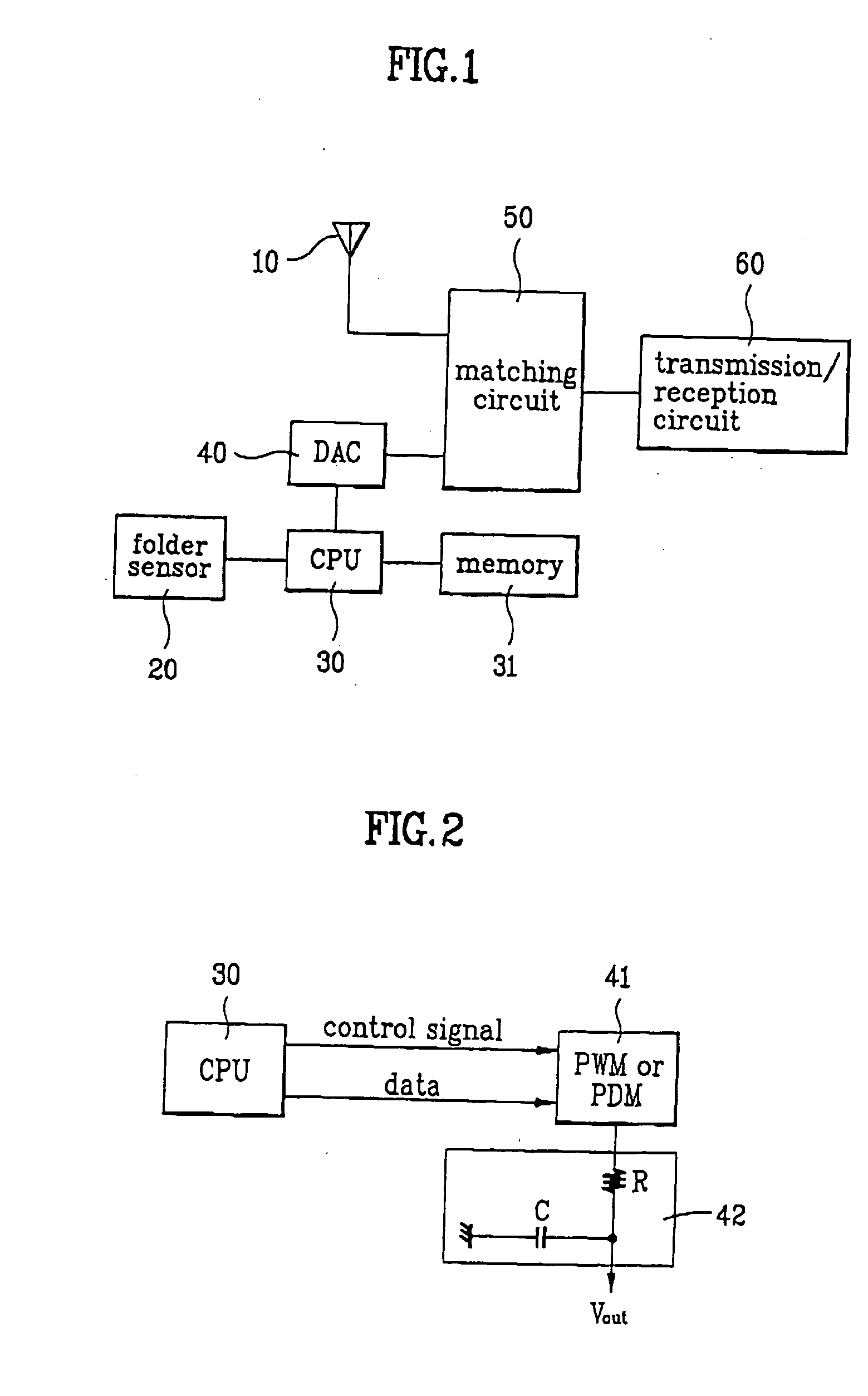
[0032]FIG. 1 illustrates a block diagram of a device for matching an antenna impedance in a portable radio telephone in accordance with a first preferred embodiment.

[0033] Referring to FIG. 1, the device for matching an antenna impedance in a portable radio telephone in accordance with a first preferred embodiment includes an antenna 10, a folder sensor 20, a central processing unit (CPU) 30, a Digital-to-Analog Converter (DAC) 40, a matching circuit 50, transmission / reception circuit 60, and a non-volatile memory 31. The antenna 10 receives a radio wave signal from the air and provides the signal to a matching circuit 50, or transmits a signal from the matching circuit 50 to the air. The folder sensor 20 has a permanent magnet and a magnetic sensor for sensing a folded or unfolded state of a casing of the portable radio telephone, and communicating the state to the CPU 30. The non-volatile memory 31 stores a voltage value corresponding to a state of the folder sensor, and the CPU ...

second embodiment

[0042] A device for matching an antenna impedance in a portable radio telephone in accordance with a second preferred embodiment will be explained. FIG. 6 illustrates a block diagram of a device for matching an antenna impedance in a portable radio telephone in accordance with a second preferred embodiment, FIG. 7A illustrates an outer appearance of a device for matching an antenna impedance in a portable radio telephone in accordance with a second preferred embodiment, and FIG. 7B illustrates a circuit of the CPU and the antenna sensor in FIG. 7A.

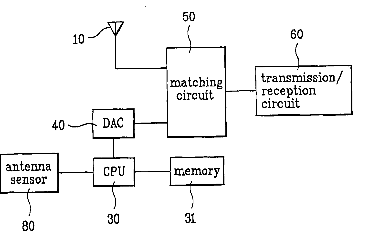
[0043] Referring to FIG. 6, the device for matching an antenna impedance in a portable radio telephone in accordance with a second preferred embodiment includes an antenna 10, an antenna sensor 80, a CPU 30, a DAC 40, a matching circuit 50, a transmission / reception circuit 60, and a non-volatile memory 31. The antenna sensor 80 senses the antenna 10 being extracted out of the case or retracted into the casing. And, the rest of the parts i...

third embodiment

[0048] A device for matching an antenna impedance in a portable radio telephone in accordance with a third preferred embodiment will be explained. FIG. 8 illustrates a block diagram of a device for matching an antenna impedance in a portable radio telephone in accordance with a third preferred embodiment.

[0049] Referring to FIG. 8, the device for matching an antenna impedance in a portable radio telephone in accordance with a third preferred embodiment includes an antenna 10, a folder sensor 20, an antenna sensor 80, a CPU 30, a DAC 40, a matching circuit 50, a transmission / reception circuit 60, and a non-volatile memory 31. The folder sensor 20 senses a folded or unfolded state of a telephone casing, the antenna sensor 80 senses whether the antenna is extracted or retracted from / to the telephone, and respectively informs the CPU 30. The non-volatile memory 31 stores voltage values for optimal antenna impedance matching according to casing states and antenna states. The CPU 30 dete...


PUM


Abstract

A device for matching an antenna impedance in a portable radio telephone having transmission and-receiving circuits, a foldable casing enclosing the radio, the foldable casing movable between an unfolded position and a folded position, an antenna movable between an extracted position from the foldable casing and a retracted position into the foldable casing includes means for sensing whether the foldable casing is in the unfolded position and for sensing whether the antenna is in the extracted position, and for providing a sensing signal in response thereto, and means for matching an impedance of the antenna and an impedance of the radio in response to the sensing signal, thereby making an optimal matching of impedances between the antenna and the radio according to the states of the folder casings and the antenna, and according to the transmission / reception mode.

Description

CROSS REFERENCES TO RELATED APPLICATIONS [0001] This application claims the benefit of Korean patent application No. 1999-30587, filed on Jul. 27, 1999, the entirety of which is hereby incorporated by reference for all purposes as if fully set forth herein. BACKGROUND OF THE INVENTION [0002] 1. Field of the Invention [0003] The present invention relates to a device for matching an antenna impedance in a portable radio telephone, and more particularly, to a device for matching an antenna impedance in a portable radio telephone, for maintaining an optimal antenna impedance matching state. [0004] 2. Background of the Related Art [0005] The portable radio telephone of a folder type, or a type similar to the folder type, is provided with an upper casing and a lower casing for protecting a display and a keypad. Since an antenna related impedance is varied with the state of the casing, (i.e., a folded or closed state and an unfolded or open state), the radio performance characteristics als...

Claims


Application Information

Patent Timeline
Patent Type & Authority Applications(United States)
IPC IPC(8): H01Q1/24H01Q1/12H01Q1/46H04B1/04H04B1/18
CPCH04B1/18H04B1/0458H01Q1/12H01Q1/24H01Q1/46
Inventor KIM, HONG JOO
Owner LG ELECTRONICS INC
Why Eureka
Try Eureka