Level measurement arrangement

Active Publication Date: 2005-06-23
EHNDRESS KHAUZER GMBKH KO KG
View PDF6 Cites 16 Cited by
  • Summary
  • Abstract
  • Description
  • Claims
  • Application Information

AI Technical Summary

Benefits of technology

[0010] Today microwave level measurement devices are usually mounted on a mounting section surrounding an opening of the container. Removal of the device leaves the interior of the container exposed to the environment. Correspondingly, contamination of a medium inside the container is possible. In order to prevent contamination, the container needs to be emptied before the device can be removed and the entire container needs to be cleaned and or sterilized after the device has been reinstalled on the container before the medium is reintroduced to the container. This is a costly and time intensive procedure. In some applications, for example in the bio-pharmaceutical industry, it is impossible to stop production processes, to allow for repair or replacement of microwave level measurement device. The reason for this is, that a sanitary seal would be broken. This would contaminate the product and could mean, that biological actions could be disturbed and weeks or even month of fermentation would need to be restartet.
[0011] In order to avoid these costs and the related loss of production time, there is a need for an assembly for microwave level measurement that allows removal of the microwave level measurement device, without opening the container.
[0012] In the past there have been applications for microwave level measurement devices, where engineers have physically separated microwave level measurement devices from the contents of the container, in order to protect the level measurement device from difficult measu

Problems solved by technology

In many branches of industry, containers may not be opened, when in use, due to hygienic or safety reasons.
Even air can cause contamination of a medium inside the container.
This is a costly and time intensive procedure.
This would contaminate the product and could mean, that biological actions could be disturbed and weeks or even month of fermentation would need to be restartet.
Because of the rather complex design of the assembly described, the horn antenna and thus the microwave level measurement device connected to it cannot

Method used


Image

  • Level measurement arrangement
  • Level measurement arrangement
  • Level measurement arrangement

Examples


Example

DETAILED DESCRIPTION OF THE DRAWINGS

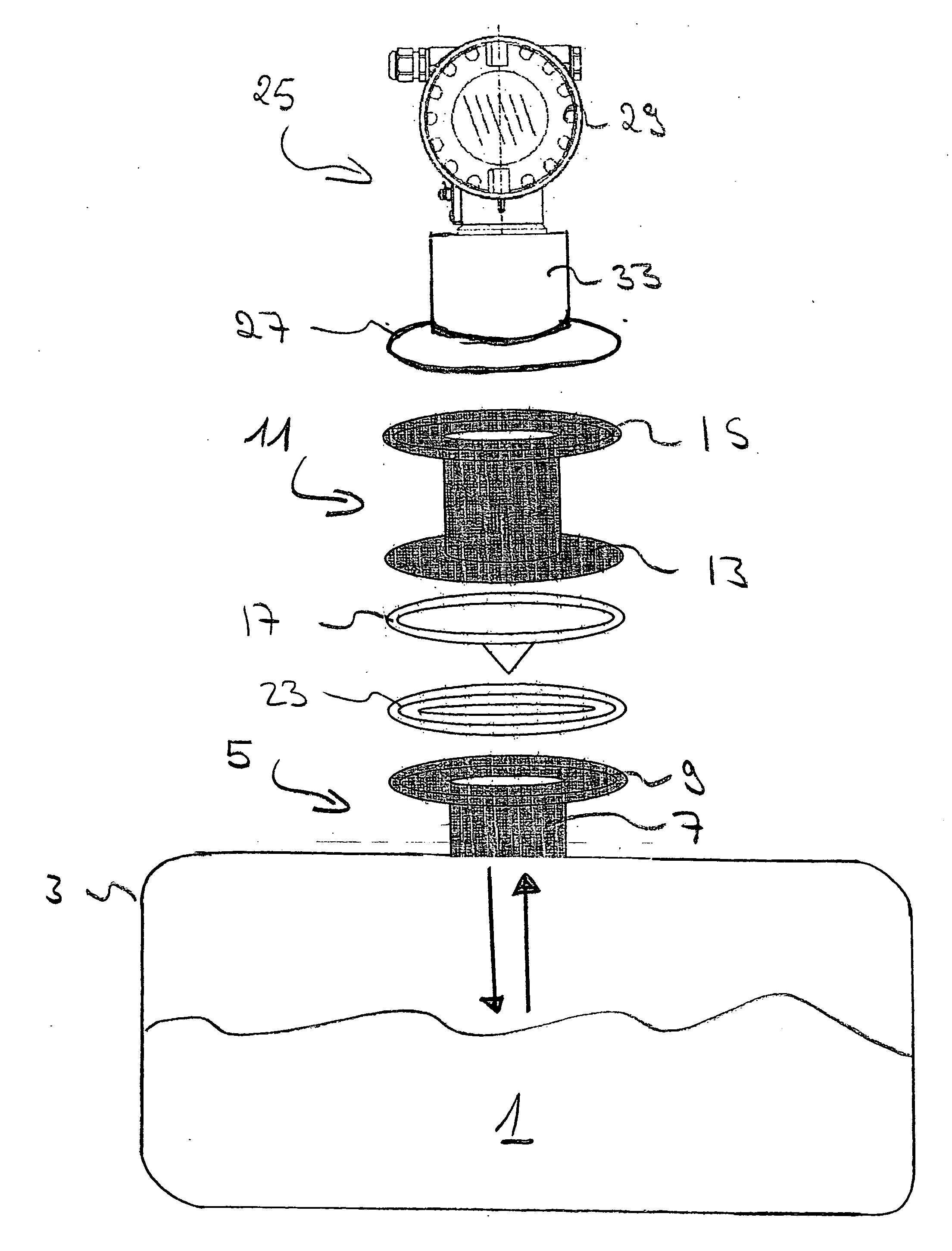
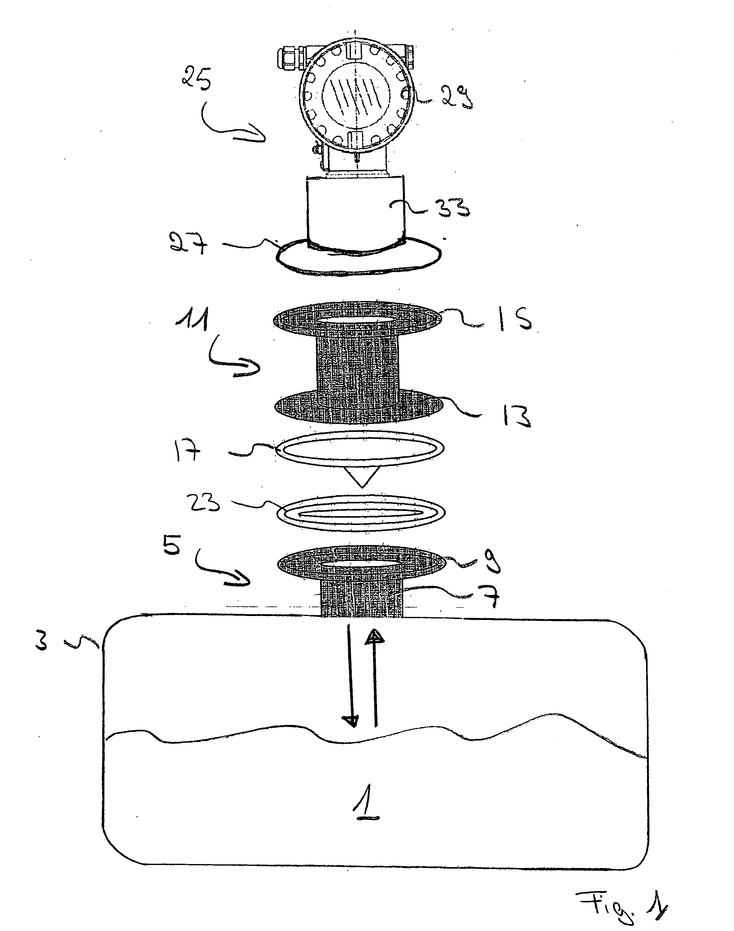
[0060]FIG. 1 shows an exploded view of an assembly for measurement of a level of a medium 1 in a container 3. A mounting section 5 is foreseen on top of the container, which surrounds an opening of the container 1. In the embodiment shown, the mounting section 5 comprises a cylindrical tube7 and a flange 9. The flange 9 is designed according to an industry standard. Preferably, a standard known under the name ‘Tri Clamp’ is used. Tri-Clamp connectors are very well accepted in industries, where high standards of hygiene need to be fulfilled.

[0061] The arrangement comprises a tubular adapter 11 comprising a first standard connector 13 located on a first end of the adapter 11 and a second standard connector 15 located on a second end of the adapter 11. Again, both connectors 13, 15 are preferably flanges designed according to the tri-clamp standard, as shown in the drawing. The adapter 11 is mounted on the mounting section 5 of the container 3 by t...


PUM


Abstract

An Arrangement for the measurement of a level of a medium in a container the arrangement allows for removal of the microwave level measurement device, without opening the container, which allows use of standard connectors. The arrangement comprises: a mounting section surrounding an opening of the container; a tubular adapter comprising a first standard connector located on a first end of the adapter and a second standard connector located on a second end of the adapter, which is mounted on the mounting section of the container by the first standard connector; an isolation window transparent for microwaves sealing a passageway through the adapter having an outer rim, which is clamped between the mounting section and the first standard connector; and a microwave level measurement device, comprising a standard process connector to be mounted on the second connector of the adapter.

Description

BACKGROUND AND SUMMARY OF THE INVENTION [0001] The present invention relates to an arrangement for measurement of a level of a medium in a container, wherein a microwave level measurement device is mounted on a mounting section surrounding an opening of the container. [0002] In many branches of industry, products are stored or processed in containers, e.g. tanks, vessels or others. It has become a very important field of measurement technology to determine a level of a medium inside a container. Level measurements are valuable means in process control as well as in process automation. [0003] One method of level measurement used today involves the use of short electromagnetic waves, in particular microwaves. Microwave level measurement devices transmit microwaves through an opening in the container toward the surface of the medium inside and receive echo waves of the transmitted microwaves. From the received echo waves an echo function representing echo amplitude as a function of the...

Claims


Application Information

Patent Timeline
IPC IPC(8): G01F23/284
CPCG01F23/284
Inventor KLEES, DANIELWESSTROM, OLAMISCIK, GREGSCHAFFER, JOE
Owner EHNDRESS KHAUZER GMBKH KO KG
Why Eureka
Try Eureka