Solar powered light assembly to produce light of varying colours

a technology of solar energy and light assembly, which is applied in the direction of outdoor lighting, sustainable buildings, material testing goods, etc., can solve the problems of not producing the uniform desired colour when required, and difficulty in adjusting the various lighting functions

Inactive Publication Date: 2005-06-23
H P M INDS
View PDF7 Cites 79 Cited by
  • Summary
  • Abstract
  • Description
  • Claims
  • Application Information

AI Technical Summary

Problems solved by technology

The abovementioned lighting apparatus have a number of disadvantages including difficulty in adjusting the various lighting functions and not producing a uniform desired colour when required to do so.

Method used


Image

  • Solar powered light assembly to produce light of varying colours
  • Solar powered light assembly to produce light of varying colours
  • Solar powered light assembly to produce light of varying colours

Examples


Embodiment Construction

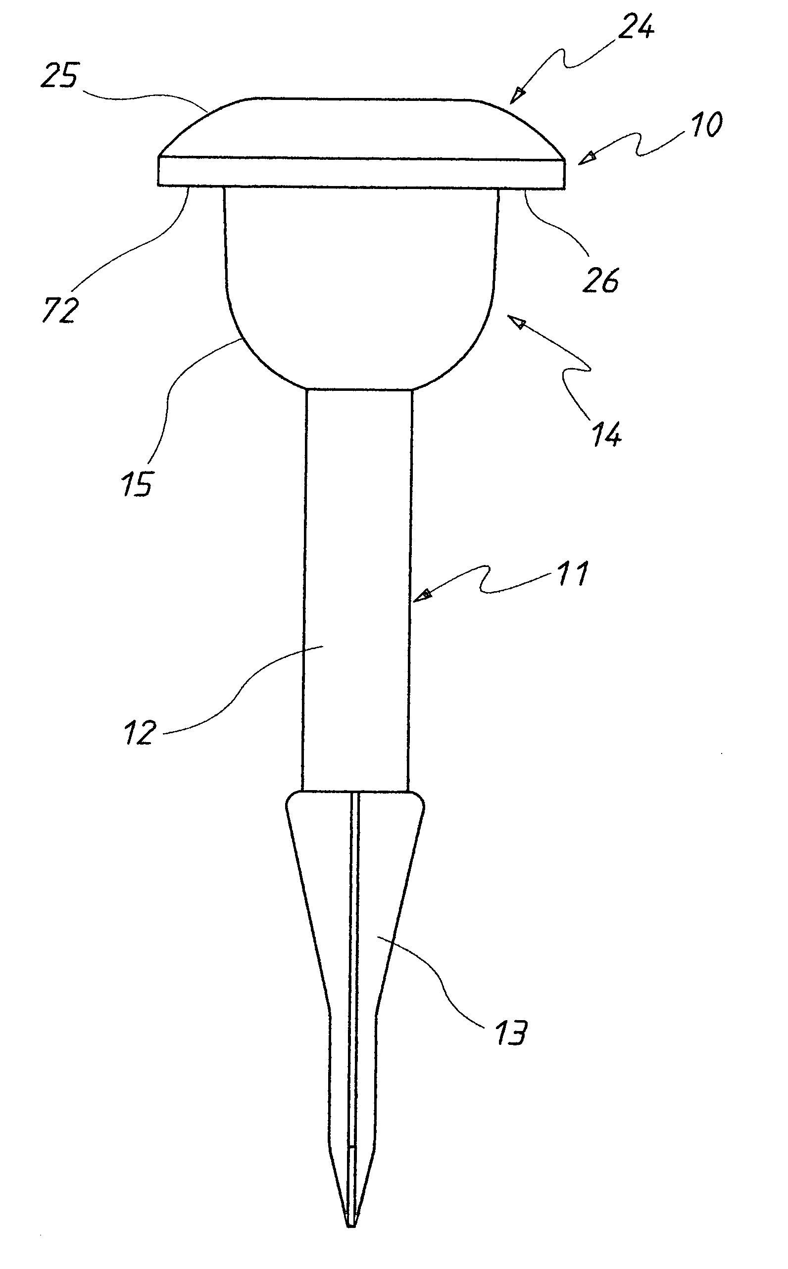
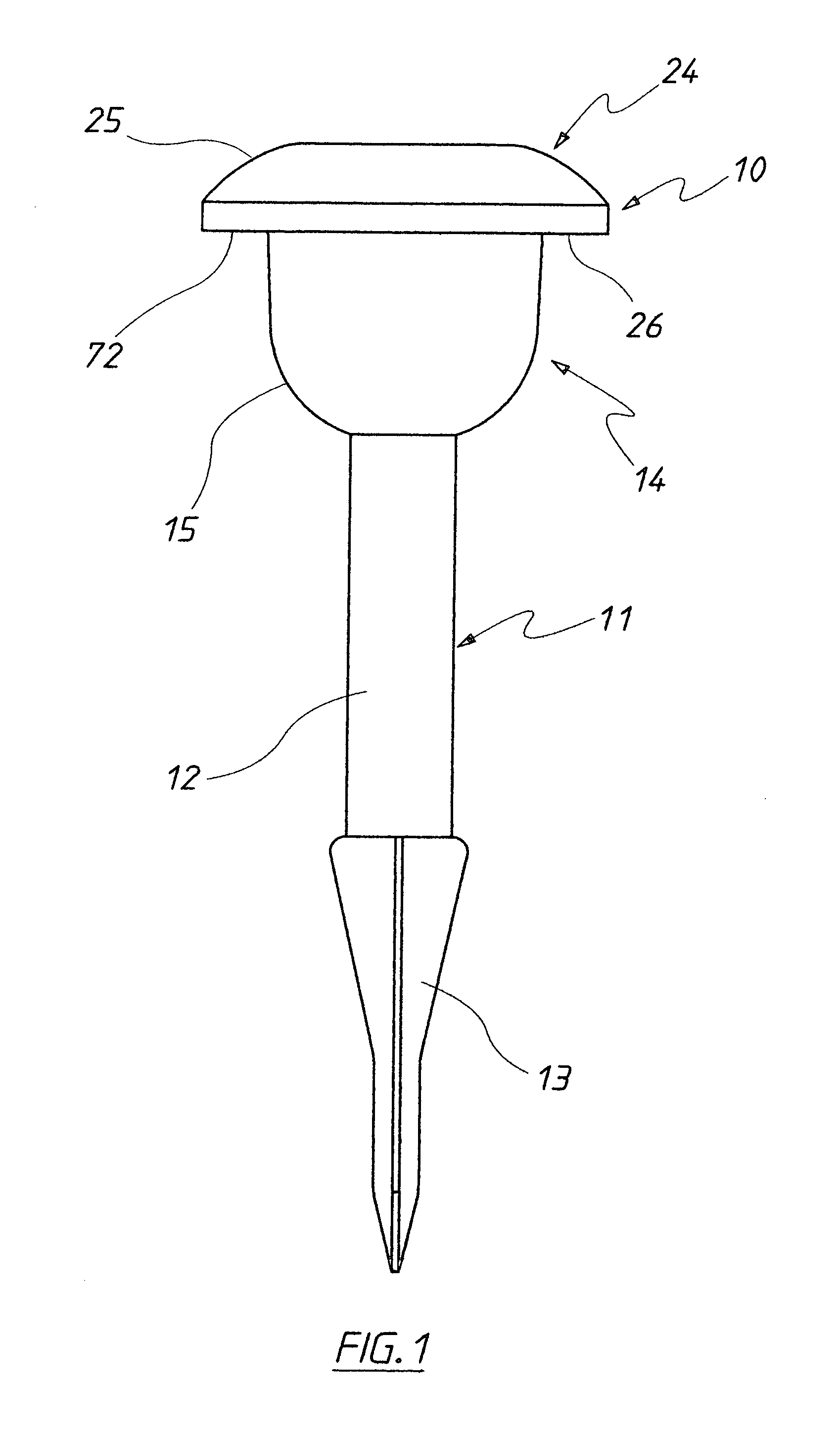
[0042] In FIGS. 1 to 9 of the accompanying drawings there is schematically depicted a lighting device 10. The device 10 of this embodiment is configured as a “garden light”. The device 10 includes a body 11 including a post 12 from the lower end from which there extends a spike 13. The spike 13 is driven into a ground surface so that the post 12 is exposed above the ground surface.

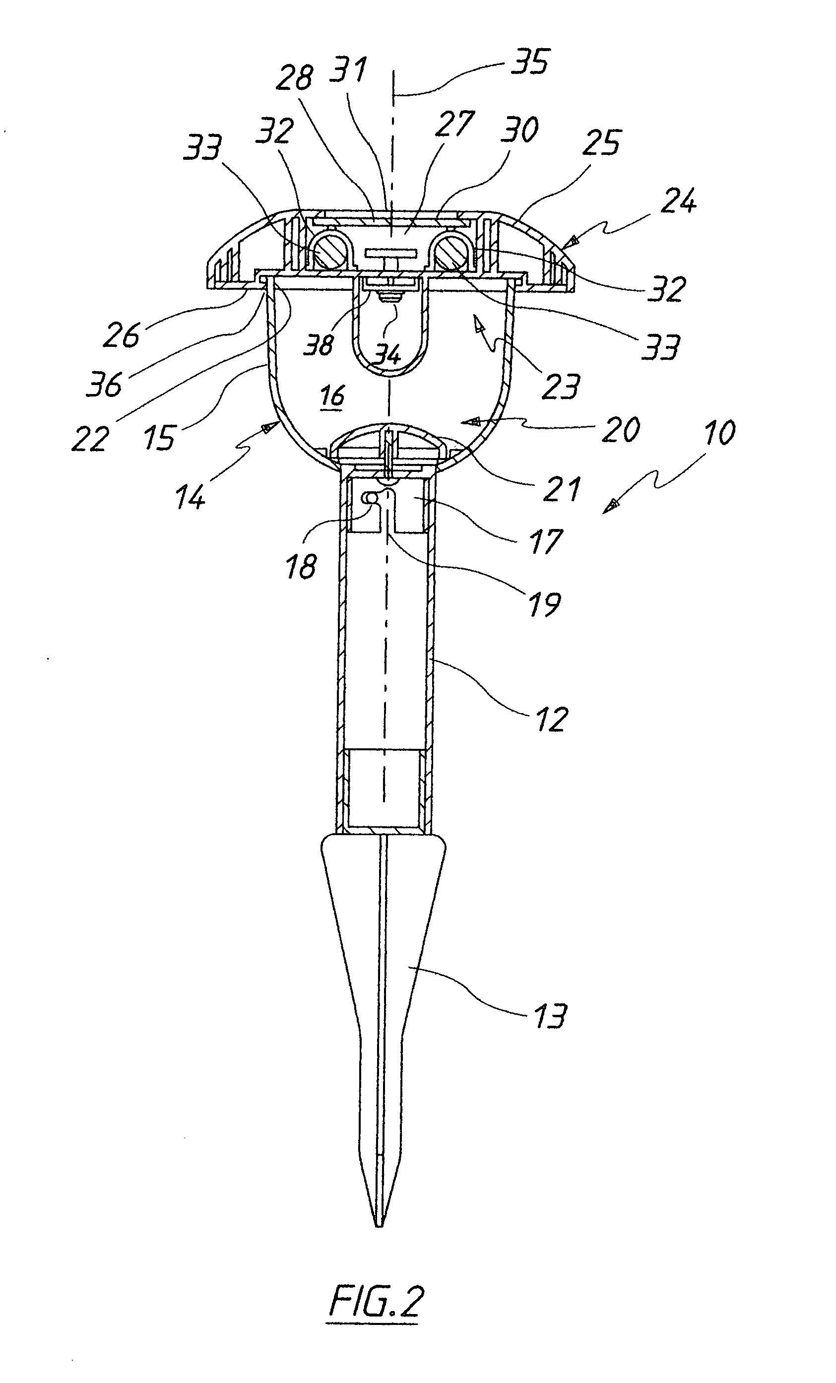
[0043] Attached to the upper end of the post 12 is a lens assembly 14. The lens assembly 14 includes a lens 15 that encompasses a chamber 16. The lower end of the lens 15 has fixed to it a “bayonet” fitting 17 that engages a shaft 18 fixed to the upper end of the post 12. The fitting 17 includes an “L” shaped slot 19 through which the shaft 18 passes to secure the lens assembly 14 to the upper end of the post 12.

[0044] The chamber 16 includes a lower portion 20 within which there is mounted an arcuate reflector 21 that is concave.

[0045] The lens 15 has a rim 22 surrounding the upper opening 23 of the le...


PUM

PropertyMeasurementUnit
colouraaaaaaaaaa
electric poweraaaaaaaaaa
poweraaaaaaaaaa

Abstract

A garden light 10 having a body (11) with a post (12), the lower end of which is provided with a spike (13). The upper end of the post (11) receives a lens assembly (12). Secured to the lens assembly (12) is a cap assembly (24) that has three LEDs that are activated to produce a varying colour light.

Description

TECHNICAL FILED [0001] The present invention relates to solar powered lights and more particularly but not exclusively to solar powered lights that produce a light of varying colour. BACKGROUND OF THE INVENTION [0002] Light devices that employ light emitting diode (LED) systems to produce a variable colour are known. Examples are described in U.S. Pat. Nos.6,459,919, 6,608,458, 6,150,774 and 6,016,038. It is also known to have “garden lights” that are solar powered. For example such garden lights include a body providing a spike that is driven into a ground surface. At the upper end of the spike there is mounted a diffuser surrounding a lamp, with the lamp being driven by rechargeable batteries and a solar cell. [0003] The abovementioned lighting apparatus have a number of disadvantages including difficulty in adjusting the various lighting functions and not producing a uniform desired colour when required to do so. OBJECT OF THE INVENTION [0004] It is the object of the present inve...

Claims


Application Information

Patent Timeline
Patent Type & Authority Applications(United States)
IPC IPC(8): F21S8/00F21S9/03F21S10/04F21V23/04G01N33/28H05B37/02H05B39/04H05B41/36
CPCF21S9/037F21S10/04F21V21/0824F21V23/0442F21W2131/10H05B37/0218F21Y2101/02H05B37/02F21S6/004F21S9/035F21W2131/109F21Y2115/10Y02B20/72Y02B20/40H05B47/10H05B47/11
Inventor RICHMOND, SIMON NICHOLAS
Owner H P M INDS
Why Eureka
Try Eureka