Portable solar light tower

a solar energy and solar panel technology, applied in the field of portable lighting systems and devices, can solve the problem of increasing the cost of using lights in a substantial way

Inactive Publication Date: 2010-09-16
CEDAR LANE TECH INC
View PDF27 Cites 47 Cited by
  • Summary
  • Abstract
  • Description
  • Claims
  • Application Information

AI Technical Summary

Problems solved by technology

With the volatility of oil prices, diesel is, at times, very expensive, causing the cost of using the lights to increase substantially.

Method used


Image

  • Portable solar light tower
  • Portable solar light tower
  • Portable solar light tower

Examples


Embodiment Construction

[0019]A portable solar light tower utilizes solar power to charge one or more batteries and then uses the batteries to power a set of lights.

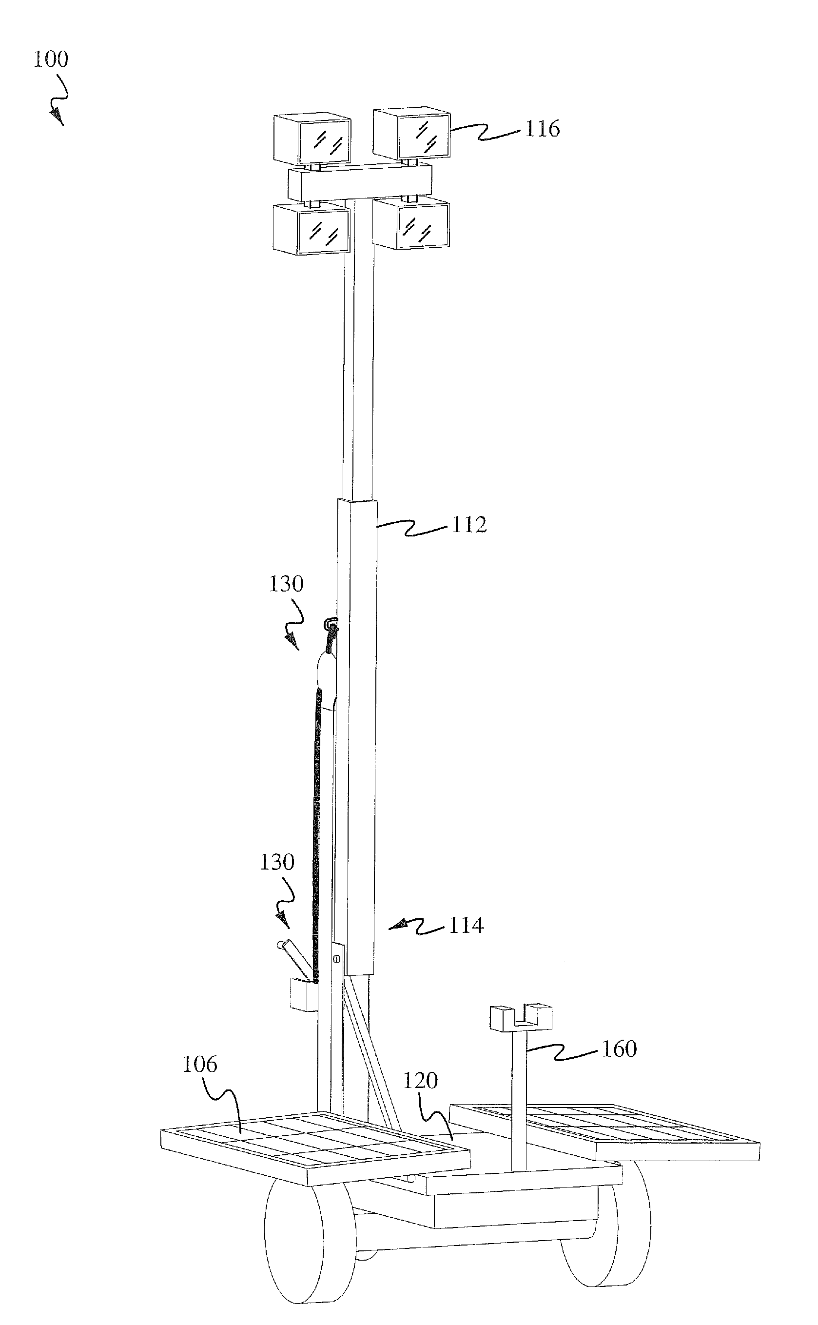
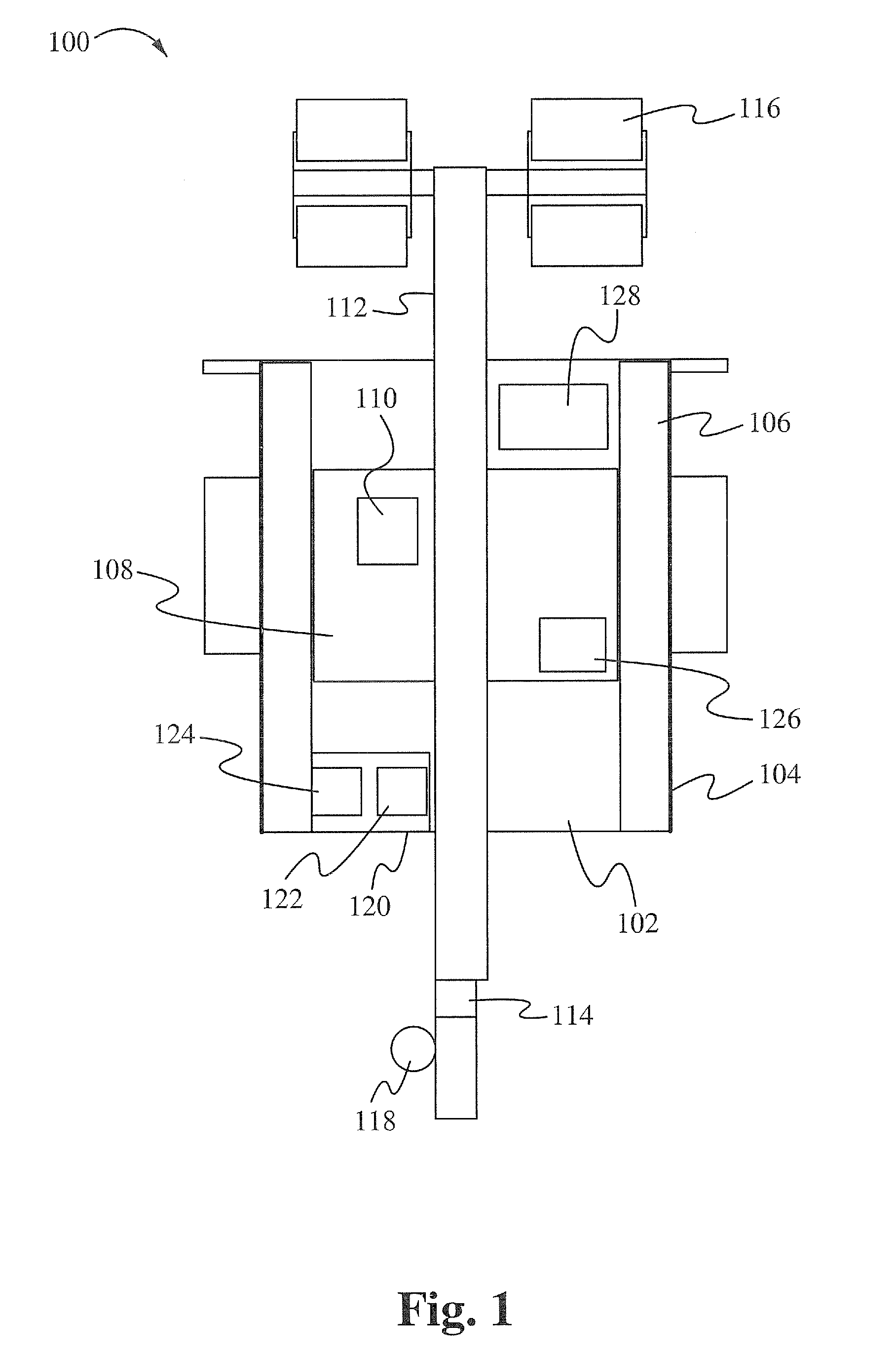
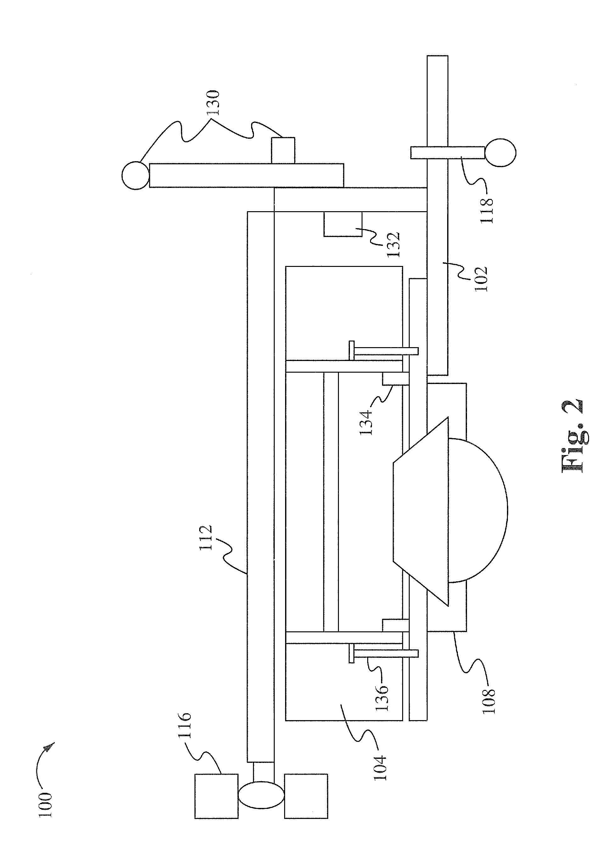
[0020]FIG. 1 illustrates a top view of a portable solar light tower 100 in a travel mode in accordance with some embodiments. The portable solar light tower 100 includes several components such as a frame 102, backplates 104, one or more solar modules 106, a battery enclosure / box 108, one or more batteries 110, a tower 112, a tower base pivot point 114, one or more lights 116, a trailer jack 118, a control enclosure 120, controls 122, a charge controller 124, jumper cables 126 and a generator 128. In the travel mode, the tower 112 is positioned in a lowered position so that the tower 112 and lights 116 do not hit objects. Additionally, in travel mode, the solar modules 106 and the backplates 104 are positioned in a closed position so that the solar modules 106 face inward and are protected with the backplates 104 facing outward.

[0021]The frame ...


PUM


Abstract

A portable solar light tower includes a trailer mounted extension tower outfitted with high output Light Emitting Diode (LED) flood lights. The portable solar light tower also includes a set of solar panels which fold up for travel mode and fold down for charging mode. A battery bank is housed in a locking compartment built into the trailer deck.

Description

CROSS-REFERENCE TO RELATED APPLICATION(S)[0001]This application claims priority under 35 U.S.C. 119(e) of the U.S. Provisional Patent Application Ser. No. 61 / 159,699, filed Mar. 12, 2009 and entitled, “PORTABLE SOLAR LIGHT TOWER,” which is hereby incorporated by reference in its entirety for all purposes.FIELD OF THE INVENTION[0002]The present invention relates to the field of lighting systems and devices. More specifically, the present invention relates to the field of portable lighting systems and devices that use solar power.BACKGROUND OF THE INVENTION[0003]Road construction is preferably done at night when traffic is low, and the affect on drivers and traffic is minimized. Other construction is performed during the night as well. However, at night, large lights or at least powerful lights are used to illuminate the work area so that the workers are able to see. These large lights are high wattage lights which run using a diesel powered generator. With the volatility of oil price...

Claims


Application Information

Patent Timeline
Patent Type & Authority Applications(United States)
IPC IPC(8): F21L4/00
CPCB60P3/18F21L14/04F21S9/03F21V21/22F21W2131/1005F21V21/26B60Q1/0029B62D63/08F21K9/30F21L4/08F21Y2101/02F21K9/20F21Y2115/10Y02B20/72
Inventor SHARPLEY, BRYAN P.WALDORF, KIRSTEN A.
Owner CEDAR LANE TECH INC
Why Eureka
Try Eureka