Artificial solar light system using a light emitting diode

a technology of solar light and diodes, which is applied in the field of artificial solar light systems, can solve the problems of difficult to represent the characteristics of a color temperature of real solar light, difficult to represent the same light emission effect as the sun with time, and many side effects

Inactive Publication Date: 2009-10-08
SEOUL SEMICONDUCTOR
View PDF12 Cites 46 Cited by
  • Summary
  • Abstract
  • Description
  • Claims
  • Application Information

AI Technical Summary

Benefits of technology

[0017]According to the present invention described above, it is possible to provide an artificial solar light system using light emitting diodes, which can represent the same light emission effects

Problems solved by technology

Generally, in places into which solar light is difficult to come, i.e., basements or other closed spaces, various symptoms of side effects (such as undergrowth, skin diseases, and psychological anxieties) may occur due to an insufficient amount of sunshine.
However, since the incandescent lamp has a color temperature of about 3200 K, it is difficult to represent characteristics of a color temperature of real solar light (from about 3000 K to 7000 K) according to time zones.
Further, since color temperature indexes of the metal halide lamp and the xenon lamp are also limited to about 5000 K and 6000 K, respectively, it is impossible to represent the same light emission effects as the sun with time.
However, there is a disadvanta

Method used


Image

  • Artificial solar light system using a light emitting diode
  • Artificial solar light system using a light emitting diode
  • Artificial solar light system using a light emitting diode

Examples


first embodiment

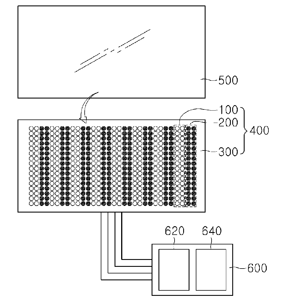
[0023]FIG. 1 is a conceptual view showing an artificial solar light system using light emitting diodes according to the present invention.

[0024]As shown in FIG. 1, the artificial solar light system using light emitting diodes according to the first embodiment of the present invention includes a light source module 400, a diffusion globe 500 provided on the light source module 400, and a control unit 600 for controlling the light source module 400.

[0025]The light source module 400 serves as a light source for the artificial solar light system using light emitting diodes according to the present invention, and includes a base plate 300 and first and second light emitting diode modules 100 and 200 that are mounted on the base plate 300.

[0026]The base plate 300 is used for fixedly mounting the first and second light emitting diode modules 100 and 200 thereon, and may be constructed to be in the form of a conventional substrate, i.e., to have a structure with an electrode pattern formed ...

second embodiment

[0040]Next, an artificial solar light system using light emitting diodes according to the present invention, which includes a global positioning system (GPS), will be described with reference to the drawings. Portions of this embodiment overlapping with those of the previous embodiment will not be described or will be briefly described.

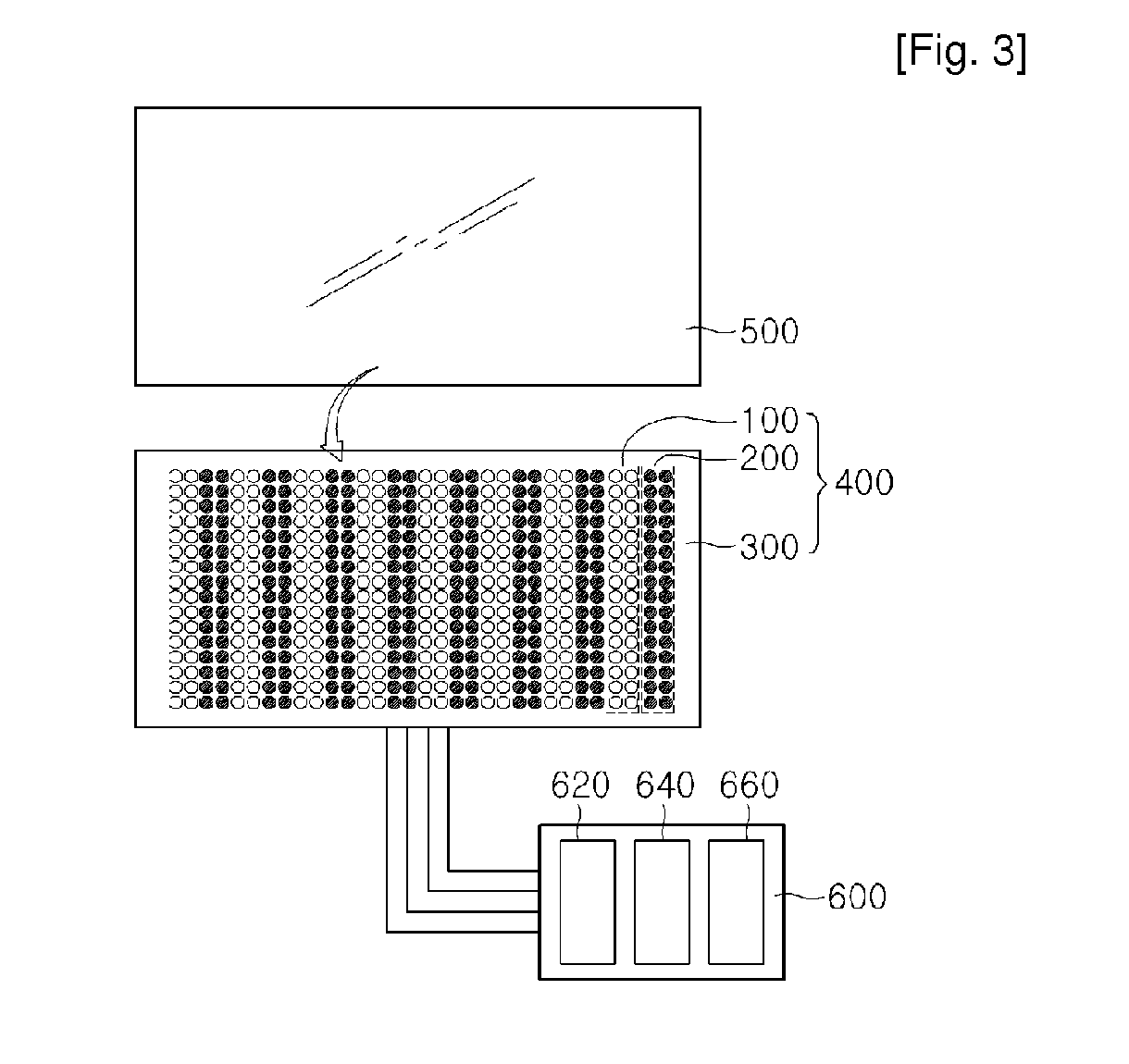
[0041]FIG. 3 is a conceptual view showing the artificial solar light system using light emitting diodes according to the second embodiment of the present invention.

[0042]As shown in FIG. 3, the artificial solar light system using light emitting diodes according to the second embodiment of the present invention includes a light source module 400, a diffusion globe 500 provided on the light source module 400, and a control unit 600 having a global positioning system 660 for controlling the light source module 400. At this time, the diffusion globe 500 may be eliminated, if necessary.

[0043]The control unit 600 is to operate the light source module 400, a...


PUM


Abstract

The present invention relates to an artificial solar light system, and more particularly, to an artificial solar light system using light emitting diodes. The present invention can provide an artificial solar light system using light emitting diodes, which can represent the same light emission effects as the sun with time. Further, the present invention can provide an artificial solar light system using light emitting diodes, which is inexpensive and is not affected by positions or climate.

Description

CROSS REFERENCE TO RELATED APPLICATIONS[0001]This application is the National Stage of International Application No. PCT / KR2007 / 003118, filed Jun. 27, 2007, and claims priority from and the benefit of Korean Patent Application No. 10-2006-0058827, filed on Jun. 28, 2006, which are both hereby incorporated by reference for all purposes as if fully set forth herein.BACKGROUND OF THE INVENTION[0002]1. Field of the Invention[0003]The present invention relates to an artificial solar light system, and more particularly, to an artificial solar light system using light emitting diodes.[0004]2. Discussion of the Background[0005]Generally, in places into which solar light is difficult to come, i.e., basements or other closed spaces, various symptoms of side effects (such as undergrowth, skin diseases, and psychological anxieties) may occur due to an insufficient amount of sunshine. Conventionally, as attempt to solve this problem, an artificial solar light system for generating artificial sol...

Claims


Application Information

Patent Timeline
IPC IPC(8): H05B37/02F21V9/00H05B44/00
CPCA01G7/045A01K63/06A61N5/0616A61N2005/0642A61N2005/0652H05B33/0866F21K9/00F21S8/006F21Y2101/02H05B33/0863A61N2005/0661F21Y2115/10H05B45/20A01G9/249F21K9/20F21V3/049F21V23/003H05B45/24
Inventor SON, WON KUKKANG, SEOK JINCHO, WON
Owner SEOUL SEMICONDUCTOR
Why Eureka
Try Eureka