Apparatus and method for time ordering events in a system having multiple time domains

a time domain and event technology, applied in the field of time ordering events, can solve the problems of difficult method for directly correlating time domains with each other and time references

Inactive Publication Date: 2005-06-23
NORTH STAR INNOVATIONS
View PDF17 Cites 35 Cited by
  • Summary
  • Abstract
  • Description
  • Claims
  • Application Information

AI Technical Summary

Problems solved by technology

For some applications, there may be no easy method for directly correlating

Method used


Image

  • Apparatus and method for time ordering events in a system having multiple time domains
  • Apparatus and method for time ordering events in a system having multiple time domains
  • Apparatus and method for time ordering events in a system having multiple time domains

Examples


Embodiment Construction

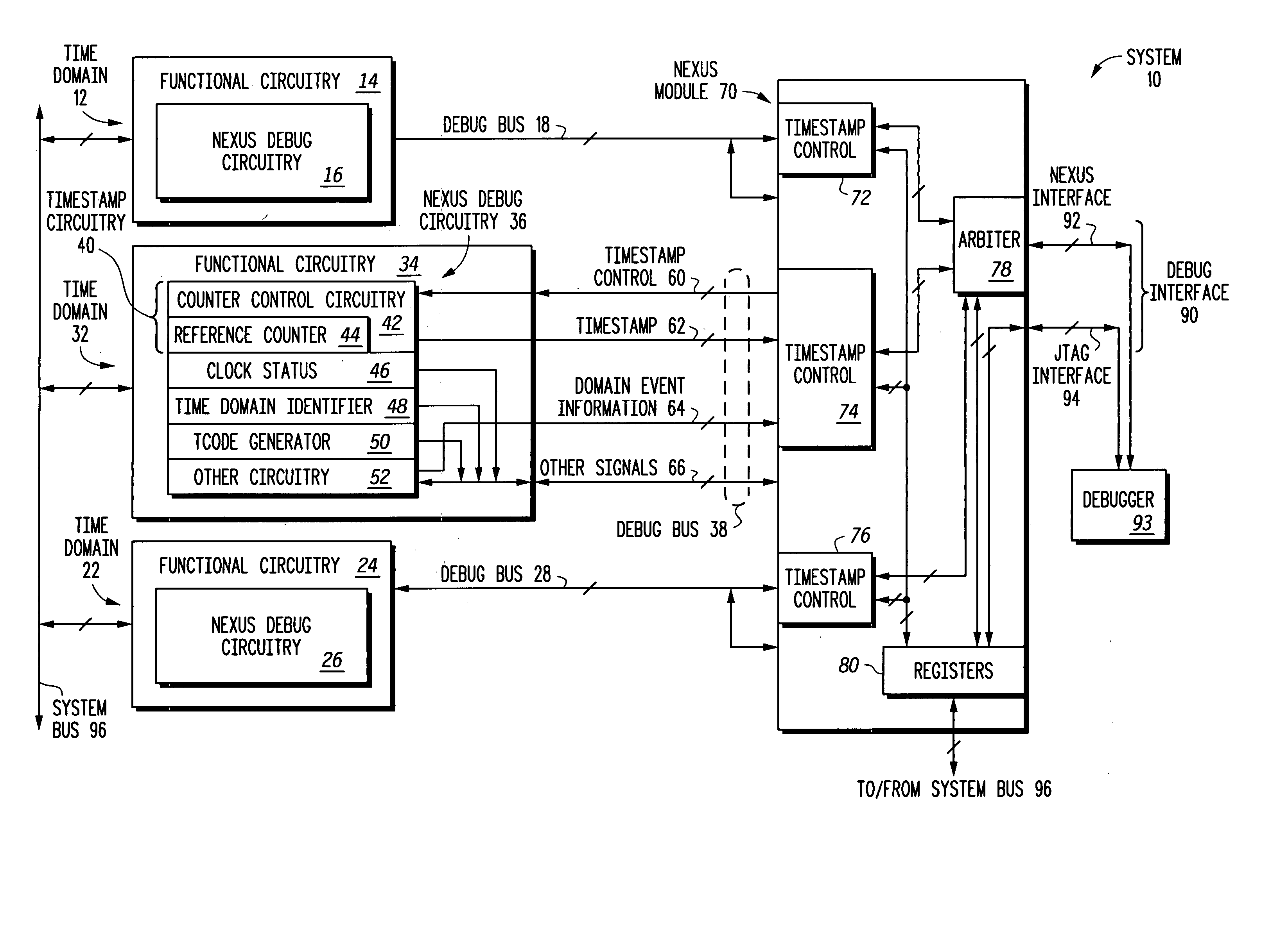
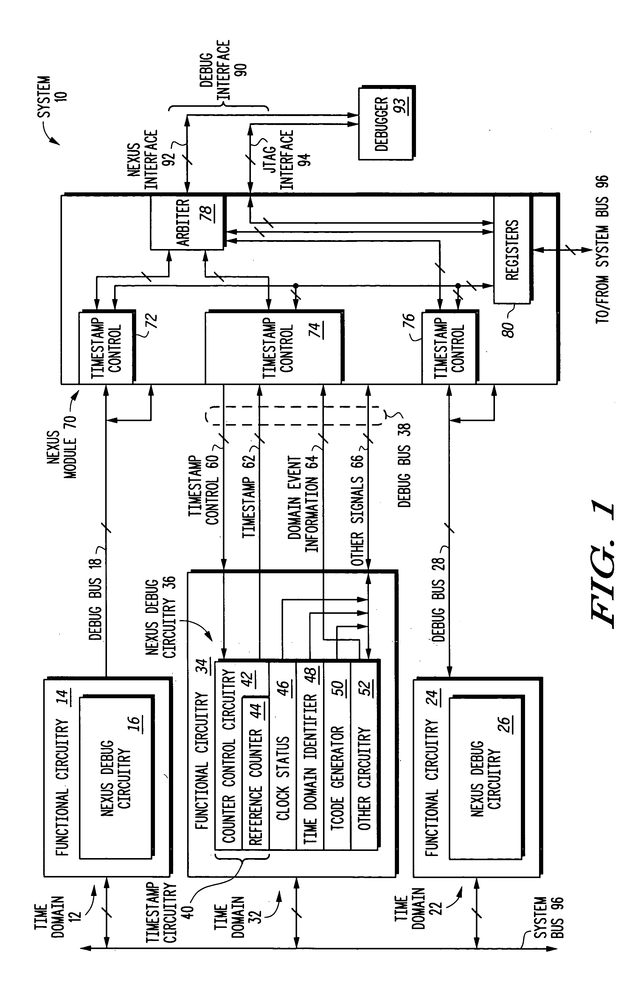
[0010] As used herein, the term “bus” is used to refer to a plurality of signals or conductors which may be used to transfer one or more various types of information, such as, for example, data, addresses, control, or status.

[0011] Illustrated in FIG. 1 is a data processing system 10 generally having a time domain 12, a time domain 32 and a time domain 22. The time domain 12 includes a module that represents functional circuitry 14. Contained within functional circuitry 14 is NEXUS debug circuitry 16 where “NEXUS”™ refers to the publicly available IEEE ISTO 5001 standard for debugging and / or emulating, and / or testing integrated circuits. Similarly, time domain 32 has functional circuitry 34 and NEXUS debug circuitry 36. Time domain 22 has functional circuitry 24 and NEXUS debug circuitry 26. One possible embodiment of the NEXUS debug circuitry 36 is illustrated in detail. It should be apparent that NEXUS debug circuitry 16 and NEXUS debug circuitry 26 may be implemented in the same...


PUM


Abstract

A system and method time orders events that occur in various portions of the system (10) where different time domains (12, 22, 32) exist. Timestamping circuitry (e.g. 40) is provided in each of a plurality of functional circuits or modules (14, 24, 34). The timestamping circuitry provides a message that indicates a point in time when a predetermined event occurs. An interface module (70) is coupled to each of the plurality of functional circuits (14, 24, 34). The interface module (70) provides control information to the plurality of functional circuits (14, 24, 34) to indicate at least one operating condition that triggers the predetermined event, and to optionally specify a message format. The interface module (70) provides a timestamping message from one, several or all time domains at a common interface port (90).

Description

FIELD OF THE INVENTION [0001] The present invention relates generally to time ordering events, and more particularly to time ordering events in a system having multiple time domains. RELATED ART [0002] Timestamping is a useful technique that may be used in a system, such as, for example, in debugging a system, to indicate when a desired event occurred in the system. Some systems, including systems which are integrated on a single integrated circuit, include a plurality of time domains. For some applications, there may be no easy method for directly correlating time domains with each other and with time references external to the system.BRIEF DESCRIPTION OF THE DRAWINGS [0003] The present invention is illustrated by way of example and not limited by the accompanying figures, in which like references indicate similar elements, and in which: [0004]FIG. 1 illustrates, in block diagram form, a system in accordance with one embodiment of the present invention; [0005]FIG. 2 illustrates, in...

Claims


Application Information

Patent Timeline
IPC IPC(8): G06F11/00
CPCG06F11/3632G06F11/3648G06F11/3636G06F11/00G06F11/28
Inventor MOYER, WILLIAM C.COLLINS, RICHARD G.FITZSIMMONS, MICHAEL D.NEARING, JASON T.
Owner NORTH STAR INNOVATIONS
Why Eureka
Try Eureka