Computer system including active system and redundant system and state acquisition method

Active Publication Date: 2005-06-30
NEC CORP
View PDF4 Cites 30 Cited by
  • Summary
  • Abstract
  • Description
  • Claims
  • Application Information

AI Technical Summary

Benefits of technology

[0007] An object of the present invention is to make it possible to acquire data indicating a state immediately before occurrence of a trouble, with little influence on normal program processing.

Problems solved by technology

In the former method, though it is relatively frequently used, there is a difficulty in reliability because processing for storing data must be performed in an unstable state after the occurrence of the trouble.
Therefore, there is a problem that overhead upon execution of the program increases and it brings about delay in normal program processing.
In particular, the problem becomes remarkable as the amount of data to be stored increases, for example, when it is a huge amount of data including all images in the main memory, files on an external memory device used by the program, and so on.

Method used


Image

  • Computer system including active system and redundant system and state acquisition method
  • Computer system including active system and redundant system and state acquisition method
  • Computer system including active system and redundant system and state acquisition method

Examples


example 1

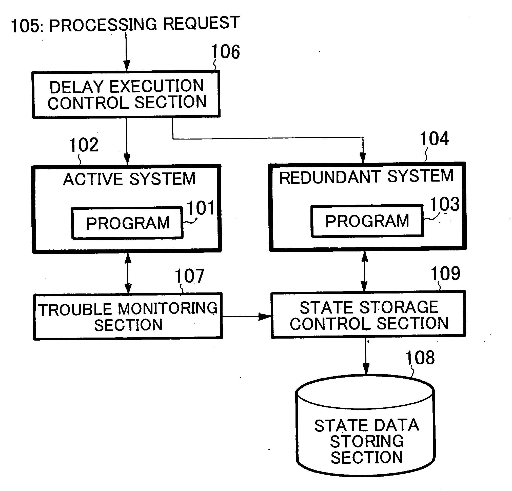
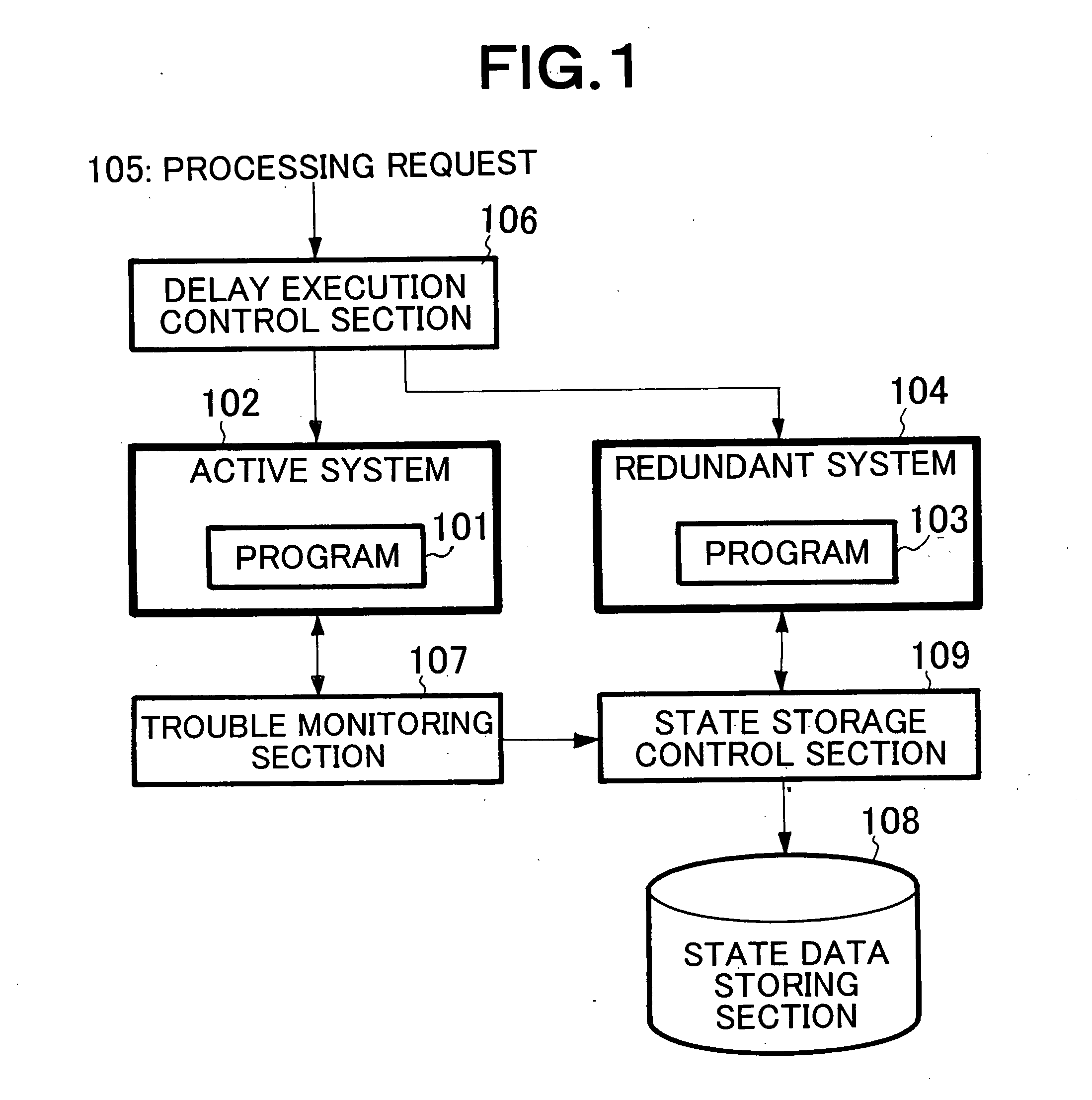
[0041] Referring to FIG. 3, a computer system according to Example 1 of the present invention is a transaction processing system, which is made up of a first processing module 1 and a second processing module 2, each constituted by a data processing machine (a computer, a central processing unit, and a processor) operating under program control; a client 3; a trouble monitoring section 4; a state storage control section 5; and a state data storing section 6. The first processing module 1 includes an active server 10, client communication means 11, transaction duplicating means 12, and an active server communication means 13. The second processing module 2 includes a redundant server 20, transaction buffer means 22, and redundant server communication means 23. In relation to FIG. 1, the active server 10 and the redundant server 20 correspond to the active system 102 and the redundant system 104, respectively. The redundant server 20 executes the same transaction processing program as...

example 2

[0056] Referring to FIG. 6, a transaction processing system according to Example 2 differs in constitution from Example 1 on the point that a timer 24 is added to the second processing module 2 in the transaction processing system according to Example 1. The timer 24 has a function of holding the value of the current time or the time elapsed from a certain time, and returning the value in response to a request from the transaction buffer means 22 and the redundant server communication means 23.

[0057] Next, an operation of Example 2 will be described with reference to the block diagram of FIG. 6 and the flowchart of FIG. 7 with laying stress on the different point from Example 1. The difference of the operation of Example 2 from the operation of Example 1 is only in the part of the operation of the second processing module 2 when no trouble occurs. As for S101 to S108 of FIG. 4 and S201 to S208 of FIG. 5 of Example 1, the same operations are performed also in this example. In place ...

example 3

[0062] Referring to FIG. 8, a transaction processing system according to Example 3 differs in constitution from Example 1 on the point that a timer 24 is added to the second processing module 2 in the transaction processing system according to Example 1. The timer 24 has a function of holding the value of the current time or the time elapsed from a certain time, and returning the value in response to a request from the transaction buffer means 22.

[0063] Next, an operation of Example 3 will be described with reference to the block diagram of FIG. 8 and the flowchart of FIG. 9 with laying stress on the different point from Example 1. The difference of the operation of Example 3 from the operation of Example 1 is only in the part of the operation of the second processing module 2 when no trouble occurs. As for S101 to S108 of FIG. 4 and S201 to S208 of FIG. 5 of Example 1, the same operations are performed also in this example. In place of the operation in and after S109 of FIG. 4, th...


PUM


Abstract

To make it possible to store a state immediately before occurrence of a trouble with little influence on normal program processing, separately from an active system in which a program operates, a redundant system is provided in which the same program as the program operates in the same execution environment as the active system. A delay execution control section gives the redundant system the same processing request as a processing request given to the active system, with a delay. When a trouble monitoring section detects a trouble of the active system, a state storage control section acquires data indicating a state of the redundant system and stores it in a state data storing section. Because the same program is executed with a delay in the redundant system having the same execution environment as the active system, a state of the redundant system at the time when the trouble occurs in the active system is equivalent to a state immediately before the occurrence of the trouble in the active system.

Description

BACKGROUND OF THE INVENTION [0001] 1. Field of the Invention [0002] The present invention relates to a computer system, a state acquisition method, and a state acquisition program product, and in particular, to a computer system, a state acquisition method, and a state acquisition program product, having a function of storing a computer state immediately before occurrence of a trouble, for investigating causes of the trouble. [0003] 2. Description of the Related Art [0004] In general, in methods for investigating the cause of a trouble in a computer, there are a method in which data necessary for analyzing the trouble, such as contents of a memory at the time of occurrence of the trouble, is stored in a file and the data is analyzed to investigate the cause of the trouble; and a method in which data necessary for reproducing the trouble, such as contents of a memory immediately before occurrence of the trouble, is stored in a file and the trouble is reproduced using the data to inve...

Claims


Application Information

Patent Timeline
IPC IPC(8): G06F11/00G06F11/20
CPCG06F11/2025G06F11/1695
Inventor NAKAMURA, NOBUTATSUHIRAIKE, RYUICHI
Owner NEC CORP
Why Eureka
Try Eureka