System and method for aligning and supporting interconnect systems

a technology of interconnection system and system, applied in the direction of electrical apparatus casing/cabinet/drawer, coupling device connection, instrument, etc., can solve the problems of more stubbing and problems that have arisen

Inactive Publication Date: 2005-07-07
IBM CORP
View PDF7 Cites 60 Cited by
  • Summary
  • Abstract
  • Description
  • Claims
  • Application Information

AI Technical Summary

Benefits of technology

[0010] Additionally, the disclosed embodiments relate to a method of aligning a daughter card to a back plane, the method comprising: sliding the daughter card towards the back plane; lifting the front end of the daughter; lifting the back en...

Problems solved by technology

Problems have arisen, for example, with the advent of employing daughter cards such as the large massive Processor-Memory cards.
However, inherent in such an architecture are difficulties in insuring that the Processor-Memory card's edge connecters are properly aligned to the mating board's connectors to prevent damaging the interconnect...

Method used


Image

  • System and method for aligning and supporting interconnect systems
  • System and method for aligning and supporting interconnect systems
  • System and method for aligning and supporting interconnect systems

Examples


Embodiment Construction

[0024] The invention will now be described in more detail by way of example with reference to the embodiments shown in the accompanying figures. It should be kept in mind that the following described embodiments are only presented by way of example and should not be construed as limiting the inventive concept to any particular physical configuration.

[0025] Further, if used and unless otherwise stated, the terms “upper”, “lower”, “front”, “back”, “over”, “under”, and similar such terms are not to be construed as limiting the invention to a particular orientation. Instead, these terms are used only on a relative basis.

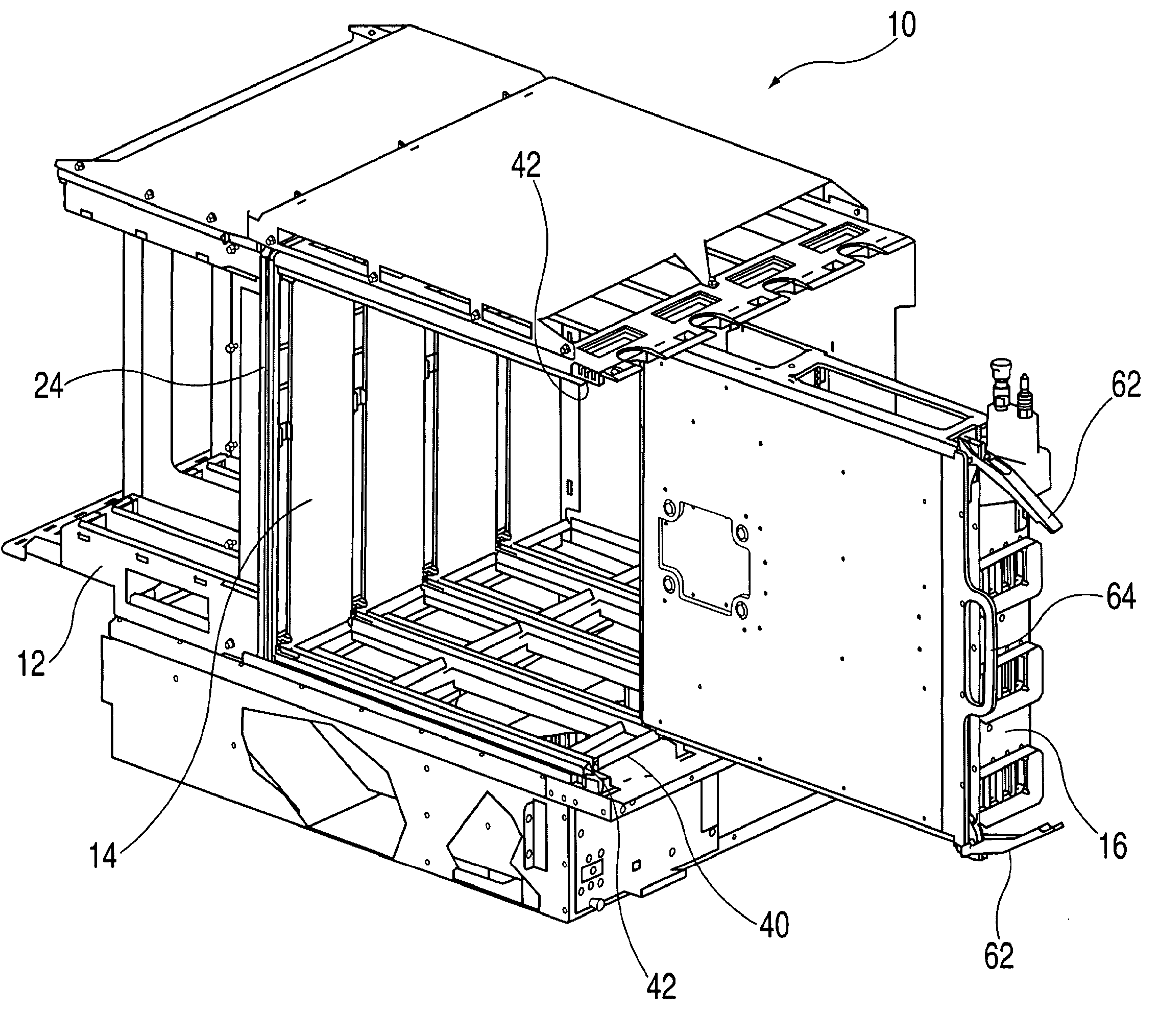
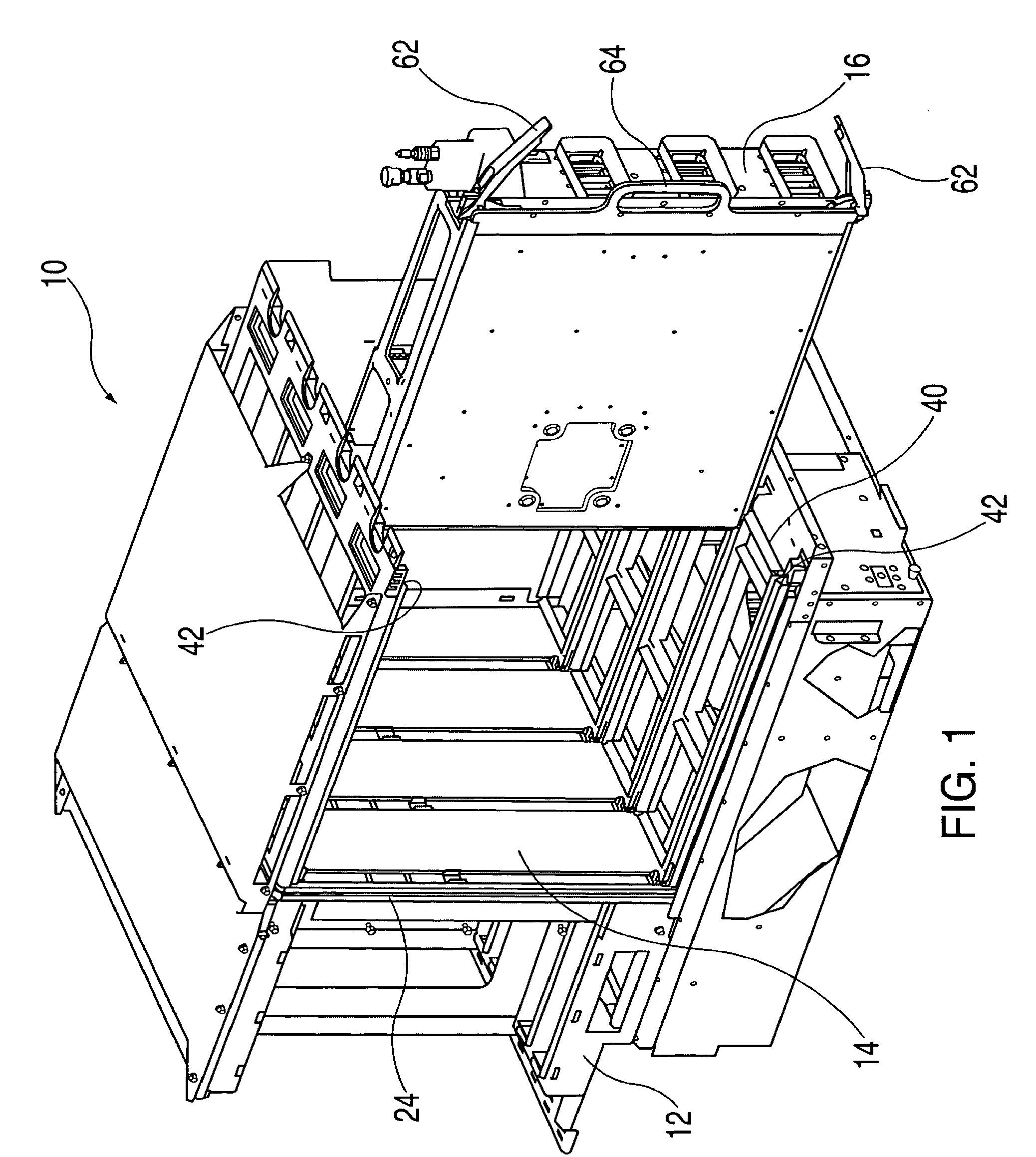
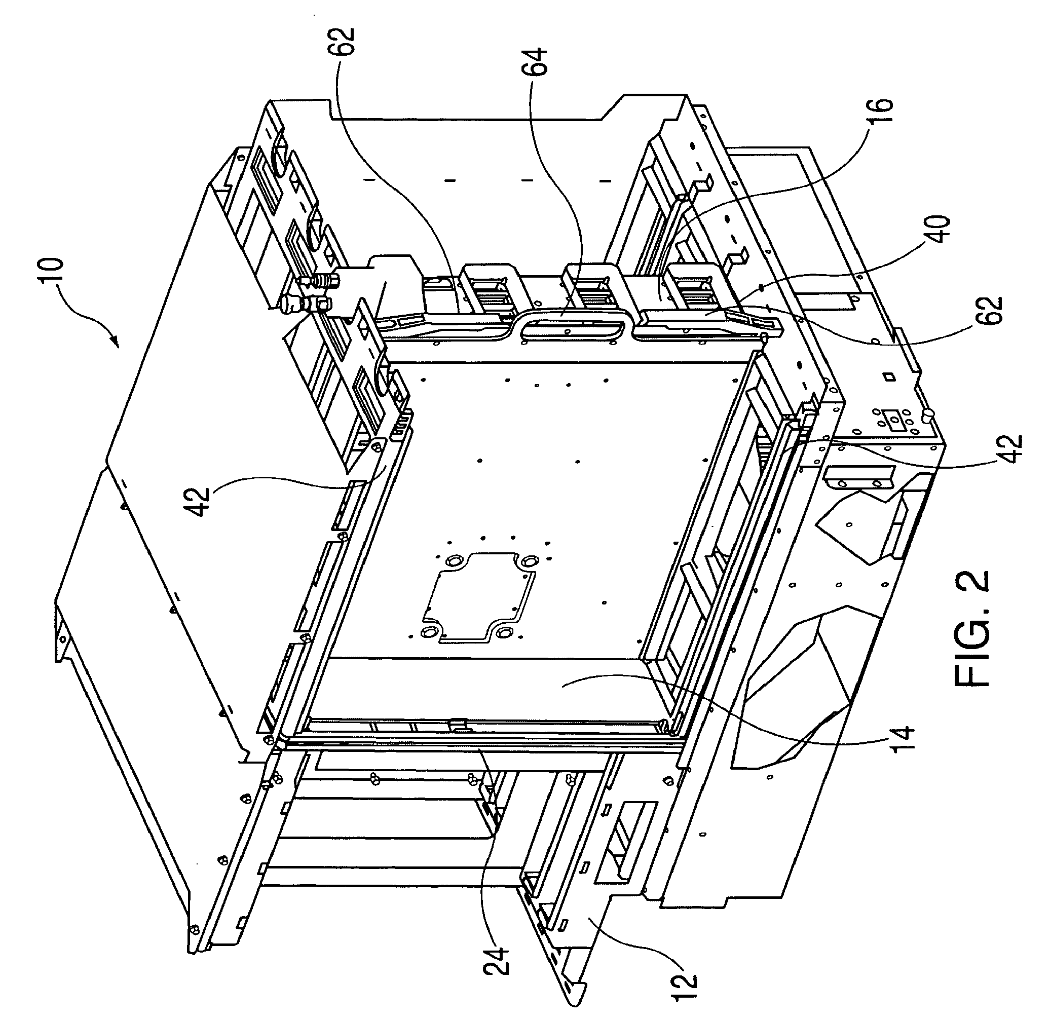
[0026]FIGS. 1 and 2 illustrate an exemplary embodiment of the invention, which includes a so-called central electronics complex 10 (CEC) of a computer system. The CEC 10 is comprised of an enclosure (such as a cage 12), a backplane or midplane 14 as illustrated, and a circuit board or daughter card, generally known as a blade or node, and may be more specifically a pro...


PUM


Abstract

An aligning apparatus comprising: a back plane, the back plane comprising at least one back plane connector; at least one daughter card, the daughter card comprising: a lower edge, the lower edge comprising a scalloped surface proximal to a rear surface of the lower edge, and a ramped surface proximal to a front surface of the lower edge; and a daughter card connector, the daughter card connector configured to be removably connectable to the back plane connector; and at least two guide rails extending from the back plane, the guide rail comprising a rear ramp and a front ramp. A method of aligning a daughter card to a back plane, the method comprising: sliding the daughter card towards the back plane; lifting the front end of the daughter; lifting the back end of the daughter card after lifting the front end of the daughter card; and providing the back end of the daughter card with a degree of freedom to lift and lower in order to align to the back plane, after lifting the back end of the daughter card.

Description

BACKGROUND OF THE INVENTION [0001] Computers are customarily provided with computer cage structures, which may comprise a sheet metal framework and which may contain a back plane. A back plane is a circuit board (e.g., mother card) or framework that supports other circuit boards, devices, and the interconnections among devices, and provides power and data signals to supported devices. The mother card may be the main circuit card in the computer, which may interconnect additional logical cards and assemblies. The computer cage structure is adapted to receive and removably support at least one and preferably a plurality of options or daughter cards (blades or nodes) which when operatively installed in their associated cage structure, upgrade the operating capabilities of the computer. For example, it is known to place an assembly, including a backplane and various circuit boards, such as a processor card, an input-output card and a so-called memory riser card, within an open cage. Thi...

Claims


Application Information

Patent Timeline
IPC IPC(8): H05K5/00H05K7/14
CPCH05K7/1454
Inventor BREHM, GEORGE W.BARTON, KEITH E.LOPARCO, JOHN J.MULLADY, ROBERT K.TOROK, JOHN G.
Owner IBM CORP
Why Eureka
Try Eureka