
Electroluminescent cable assembly and electroluminescent cable constructions included therein

a technology of electroluminescent cables and cables, applied in the direction of lighting devices, lighting apparatus details, arrangements using take-up reels/drums, etc., can solve the problems of limiting the use of such cables by ac power, and achieve the effect of convenient transportation and deploymen

Inactive Publication Date: 2005-07-14
TELDOR WIRES & CABLES
View PDF13 Cites 4 Cited by
  • Summary
  • Abstract
  • Description
  • Claims
  • Application Information

AI Technical Summary

Benefits of technology

[0004] An object of the present invention is to provide a novel electroluminescent cable assembly which may readily be used almost anywhere desired for marking-off, decoration, advertising, or other purpose. Another object of the present invention is to provide an electroluminescent cable assembly which permits the convenient transportation and deployment of the electroluminescent cable as and where desired. A further object of the present invention is to provide a novel electroluminescent cable construction for selectively emitting either visible light or infra-red non-visible light.
[0009] In the described preferred embodiment, the supporting member is a stand having a pair of legs for stably resting the reel drum on a flat horizontal surface. In addition, the assembly further comprises: mounting plate having attaching elements engageable with the pair of legs of the stand for attaching and detaching the reel drum with respect to the mounting plate. The mounting plate in the described preferred embodiment is a back plate, such as used in backpacks, and includes a body harness attached to the back plate facilitating transporting the reel to a desired location for deploying the electroluminescent cable thereat.
[0010] According to another aspect of the present invention, there is provided, an electroluminescent cable assembly, comprising: a reel constructed for winding an electroluminescent cable thereon; an electroluminescent cable wound on the reel; a stand rotatably mounting the reel for permitting the electroluminescent cable to be deployed, the stand having a pair of legs for stably resting the reel on a flat horizontal surface; and a mounting plate having attaching elements engageable with the pair of legs of the stand for attaching and detaching the reel with respect to the back plate. Preferably; but not necessarily, the mounting plate is a back plate and includes a body harness attached to the back plate facilitating transporting the reel to a desired location for deploying the electroluminescent cable thereat.
[0012] As will be described more particularly below, electroluminescent cable assemblies constructed in accordance with the foregoing features permit electroluminescent cables to be readily transported and deployed in a convenient and efficient manner at almost any location where electroluminescent lighting may be desired.

Problems solved by technology

The requirement for AC power thus limits the use of such cables since electrical power is not always available at a particular site where it may be desired to deploy the electroluminescent cable.

Method used


Image

  • Electroluminescent cable assembly and electroluminescent cable constructions included therein
  • Electroluminescent cable assembly and electroluminescent cable constructions included therein
  • Electroluminescent cable assembly and electroluminescent cable constructions included therein

Examples


Embodiment Construction

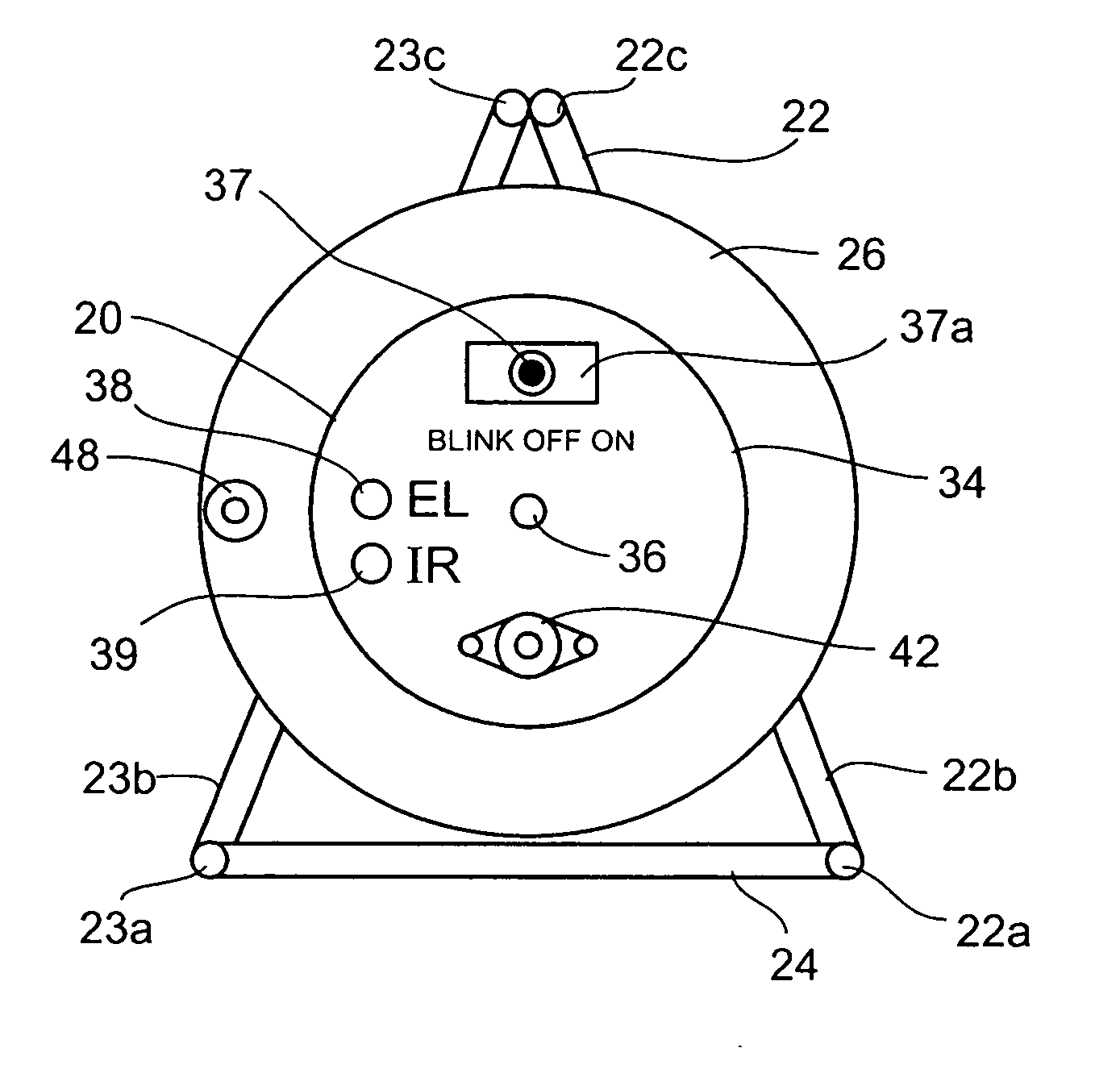
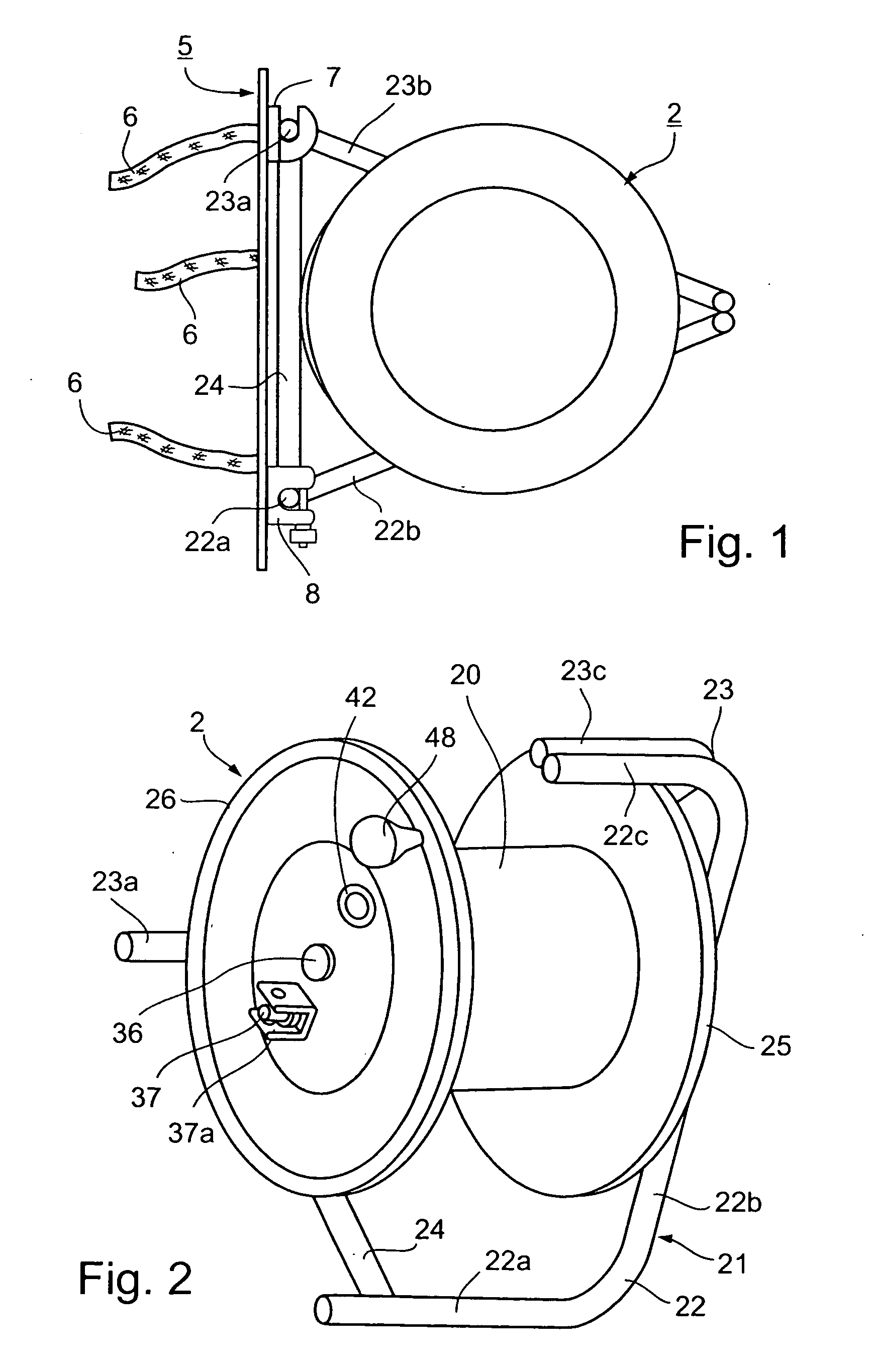
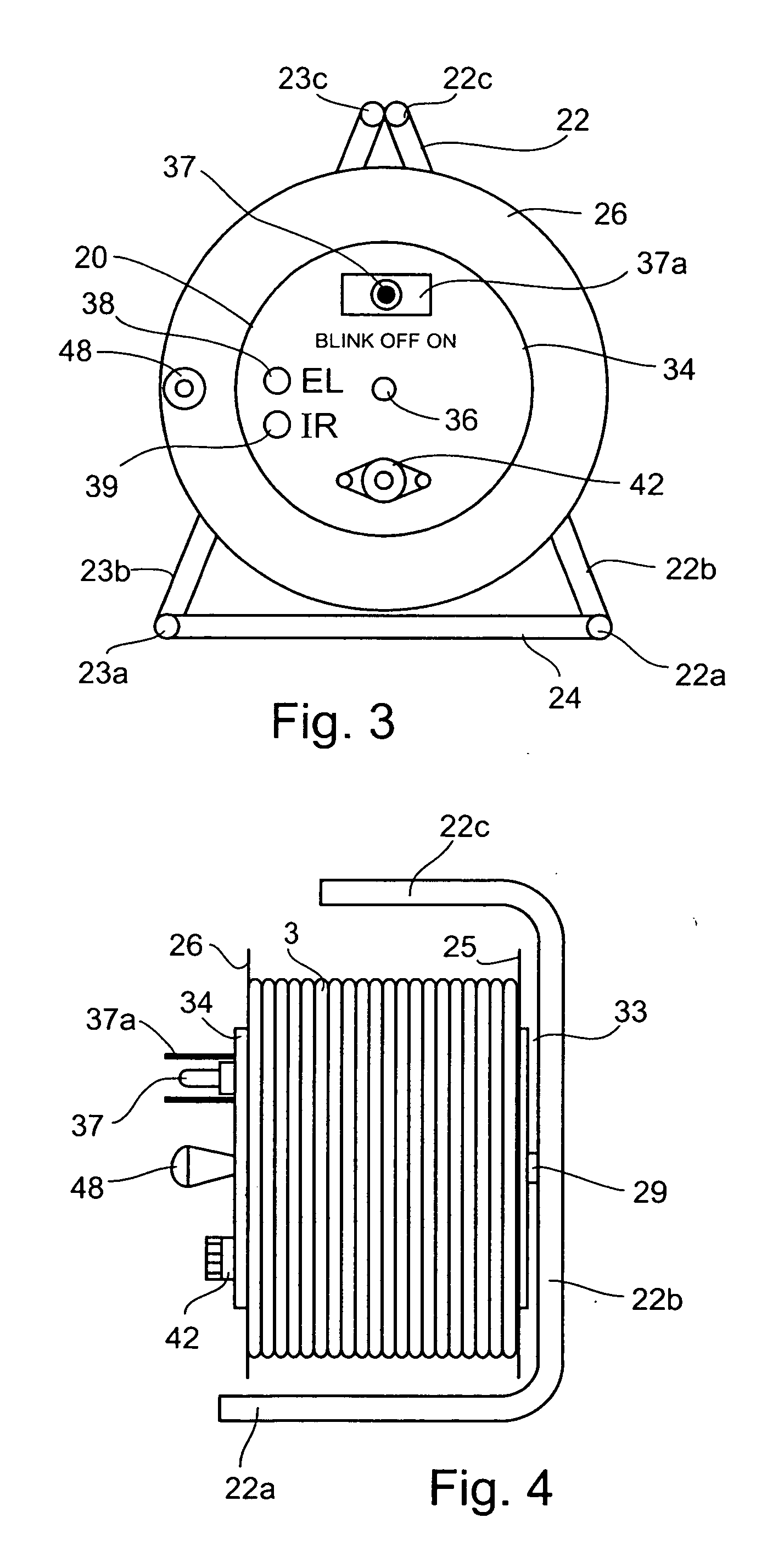
[0030] The electroluminescent cable assembly illustrated in FIG. 1 comprises a reel 2, on which is wound an electroluminescent cable 3 (FIG. 4). The reel is attached to a mounting plate, in this case a back plate 5 having a body harness 6 to enable the reel to be conveniently transported to any desired location for deployment of the electroluminescent cable. As will be described more particularly below, back plate 5 further includes attaching elements 7 and 8 which provide a convenient means for attaching the reel 2 to the back plate 5 for transportation to the deployment site, and for conveniently detaching the reel from the back plate to permit deployment of the electroluminescent cable at the desired site.

[0031] The construction of the reel 2 is more particularly illustrated in FIGS. 2-7. It includes a cylindrical drum 20 rotatably mounted on a stand 21 constituted of three frame members 22, 23 and 24. Frame members 22 and 23 are of the same construction. They include a pair of ...


PUM


Abstract

An electroluminescent cable assembly, includes a reel constructed for winding an electroluminescent cable thereon; an electroluminescent cable wound on the reel; a supporting member rotatably mounting the reel for permitting the electroluminescent cable to be deployed therefrom; and a self-contained power supply carried by the reel so as to be rotated therewith for supplying electrical power to the electroluminescent cable when deployed from the reel.

Description

FIELD AND BACKGROUND OF THE INVENTION [0001] The present invention relates to electroluminescent cable assemblies, namely to cable assemblies which include electroluminescent fibers having a phosphor which generates light when subjected to an electrical field. The invention also relates to electroluminescent cable constructions particularly useful in such assemblies. [0002] Electroluminescent cables are well known and are gaining increasing usage where it is desired to produce a linear light source for various purposes, such as for marking-off defined areas, for building decoration, for advertising, for providing lighted directions or names, etc. Examples of known types of electroluminescent cable constructions are described in various publications including U.S. Pat. Nos. 3,819,973; 5,869,930; and 5,876,863; and International Publication Nos. WO 01 / 41511 published Jun. 7, 2001, and WO 02 / 48605, published Jun. 20, 2002, the contents of which publications are incorporated herein by r...

Claims


Application Information

Patent Timeline
Patent Type & Authority Applications(United States)
IPC IPC(8): F21V9/16H02G11/02
CPCH02G11/02
Inventor HADAR, ITZHAK
Owner TELDOR WIRES & CABLES
Features
  • Generate Ideas
  • Intellectual Property
  • Life Sciences
  • Materials
  • Tech Scout
  • Unparalleled Data Quality
  • Higher Quality Content
  • 60% Fewer Hallucinations
Learn More