Method and apparatus for cellular communication over data networks

a technology of data network and cellular communication, applied in the field of wireless communication, can solve the problems of significant source of degradation, limited in certain regards, and degraded signal quality between a cellular base station and a handset under certain circumstances, so as to increase the possible number of available radio transceivers and reduce the number of packet streams

Inactive Publication Date: 2005-07-21
LUCENT TECH INC
View PDF11 Cites 166 Cited by
  • Summary
  • Abstract
  • Description
  • Claims
  • Application Information

AI Technical Summary

Benefits of technology

[0010] For uplink signals, the radio transceivers receive uplink signals from a mobile user, the transceivers convert it to a digital format and generate packets of the coded signals and forward them through the network to the aforementioned switches and then to the BSI and CMU for transmission through the traditional wireless network to an intended recipient. In another embodiment, lo in order to increase the possible number of available radio transceivers, one or more special summing nod

Problems solved by technology

Since such cellular telephones are essentially radios, it is well known that signal quality between a cellular base station and a handset degrades under certain circumstances.
The most significant source of degradation occurs when a user moves from an outside location to an indoor location where the radio signals are required to pass through or around various obstructions.
While DAS systems are advantageous in many aspects, they are limited in certain regards.
Thus, installation expense is relatively high.
Additionally, such systems are not flexibly expandable and there is typica

Method used


Image

  • Method and apparatus for cellular communication over data networks
  • Method and apparatus for cellular communication over data networks
  • Method and apparatus for cellular communication over data networks

Examples


Embodiment Construction

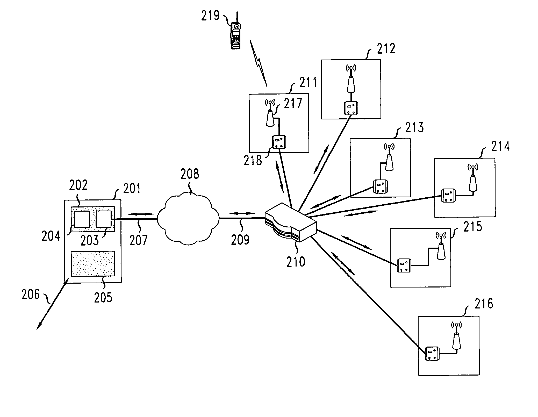
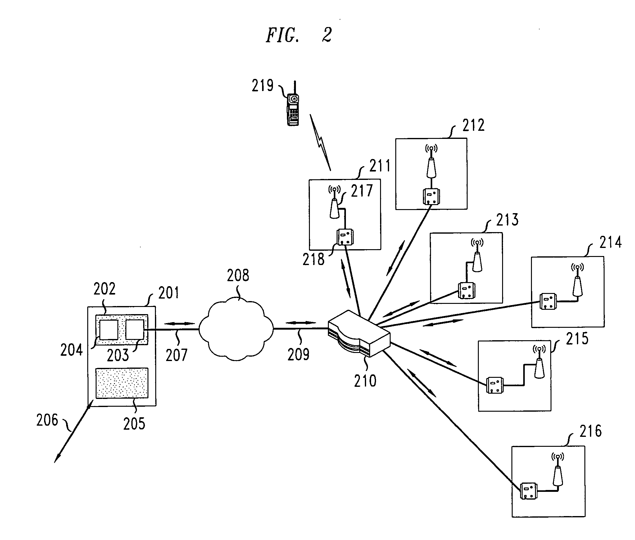
[0014]FIG. 2 shows an in-building communications network in accordance with the principles of the present invention. In the network of FIG. 2, base station 201 sends and receives messages from a wireless network via path 206. Base station 201 is, for example, similar to a base station used in a traditional CDMA network such as a OneBTS base station manufactured by Lucent Technologies, Murray Hill, N.J. One skilled in the art will recognize that such a base station traditionally has three main components: 1) a network interface for interfacing with the other components of the cellular network (e.g., a radio network controller (RNC)); 2) a digital baseband shelf typically having a processor (e.g., a CDMA modem unit (CMU)) for coding and decoding incoming and outgoing message traffic, as well as a radio (e.g., a Universal CDMA Radio (UCR)) for modulating / demodulating the coded digital message traffic onto / from a carrier signal; and 3) an RF shelf for amplifying the modulated signal and...


PUM


Abstract

Cellular signals or other wireless signals/messages are introduced into a building or to an outside location by transmitting packets corresponding to those signals over a data network and low cost cables to designated locations within the data network. Once the designated packets containing the signals reach the destination, they are then broadcast over the air to a terminal capable of receiving the wireless message. In a first embodiment, an in-building gigabit Ethernet network, such as that currently existing presently in many buildings, is used to distribute radio signals indoors. Instead of transmitting the radio signals over the air from a repeater connected to a base station, coded baseband signals generated by the coding processor (e.g., a CDMA Modem Unit) in the base station are packetized and sent over the Ethernet network to radio processing equipment and antennas distributed throughout the building. The radio processing equipment strips the packet headers from the baseband signal packets so those signals can be broadcast via the antennas to one or more mobile terminals.

Description

CROSS REFERENCE TO RELATED APPLICATIONS [0001] This application claims priority to U.S. Provisional Patent Application Ser. No. 60 / 536871 filed Jan. 16, 2004.FIELD OF THE INVENTION [0002] The present invention is related generally to wireless communications in buildings. BACKGROUNDS OF THE INVENTION [0003] Wireless communications systems are becoming an increasingly integral aspect of modern communications. In fact, recent trends show that an increasing number of users are replacing all wire-line methods of communications with their wireless counterparts such as, for example, cellular telephones in place of traditional wire-line telephones. Since such cellular telephones are essentially radios, it is well known that signal quality between a cellular base station and a handset degrades under certain circumstances. The most significant source of degradation occurs when a user moves from an outside location to an indoor location where the radio signals are required to pass through or a...

Claims


Application Information

Patent Timeline
IPC IPC(8): H04L12/28H04L12/56H04W4/04H04W28/06H04W84/04H04W88/08
CPCH04W4/04H04W88/085H04W84/042H04W28/06H04W16/26
Inventor FEDER, PERETZ MOSHESKIM, JUNGSANGMA, ZHENGXIANGOLKHOVETS, ANATOLISIEGEL, ARNOLD B.SIZER, THEODORE IIZIERDT, MICHAEL GEORGE
Owner LUCENT TECH INC
Why Eureka
Try Eureka