Roller blind device

a technology of roller blinds and rollers, which is applied in the direction of curtain suspension devices, curtain accessories, building components, etc., can solve the problems of blinds that require a significant amount of force for operation, snap upward, and unfavorable operation

Inactive Publication Date: 2005-07-28
TUSSINGER PHILIPP
View PDF4 Cites 21 Cited by
  • Summary
  • Abstract
  • Description
  • Claims
  • Application Information

AI Technical Summary

Problems solved by technology

These roller blinds require a significant amount of force for operation and frequently snap upward in an undesired manner.
Even these devices require a great amount of force and exert a heavy load on the structural components.
The considerable insertion dimensions necessitated by the construction are disadvantageous in the known solutions.
An insertion into customary double-glass windows with a 16 mm glass interval is possible with these devices, but a significant part of the original window area is lost, which reduces the incidence of light since a significant frame width is necessary for covering the functionally important parts.
Moreover, a significant motor power with corresponding current consumption and corresponding heat waste, as well as large construction dimensions, are required, also necessitated by the design.
Finally, these devices have a very complex mechanism and control, require many structural components and are therefore expensive, complicated, and have a high manufacturing cost.
They have the disadvantage that a rubber cord pull is a critical construction element, since the rubber eventually becomes brittle and tears.
In the spring arrangement, the guidance around a cam is problematic.
These publications have the disadvantage that two

Method used


Image

  • Roller blind device
  • Roller blind device
  • Roller blind device

Examples


Embodiment Construction

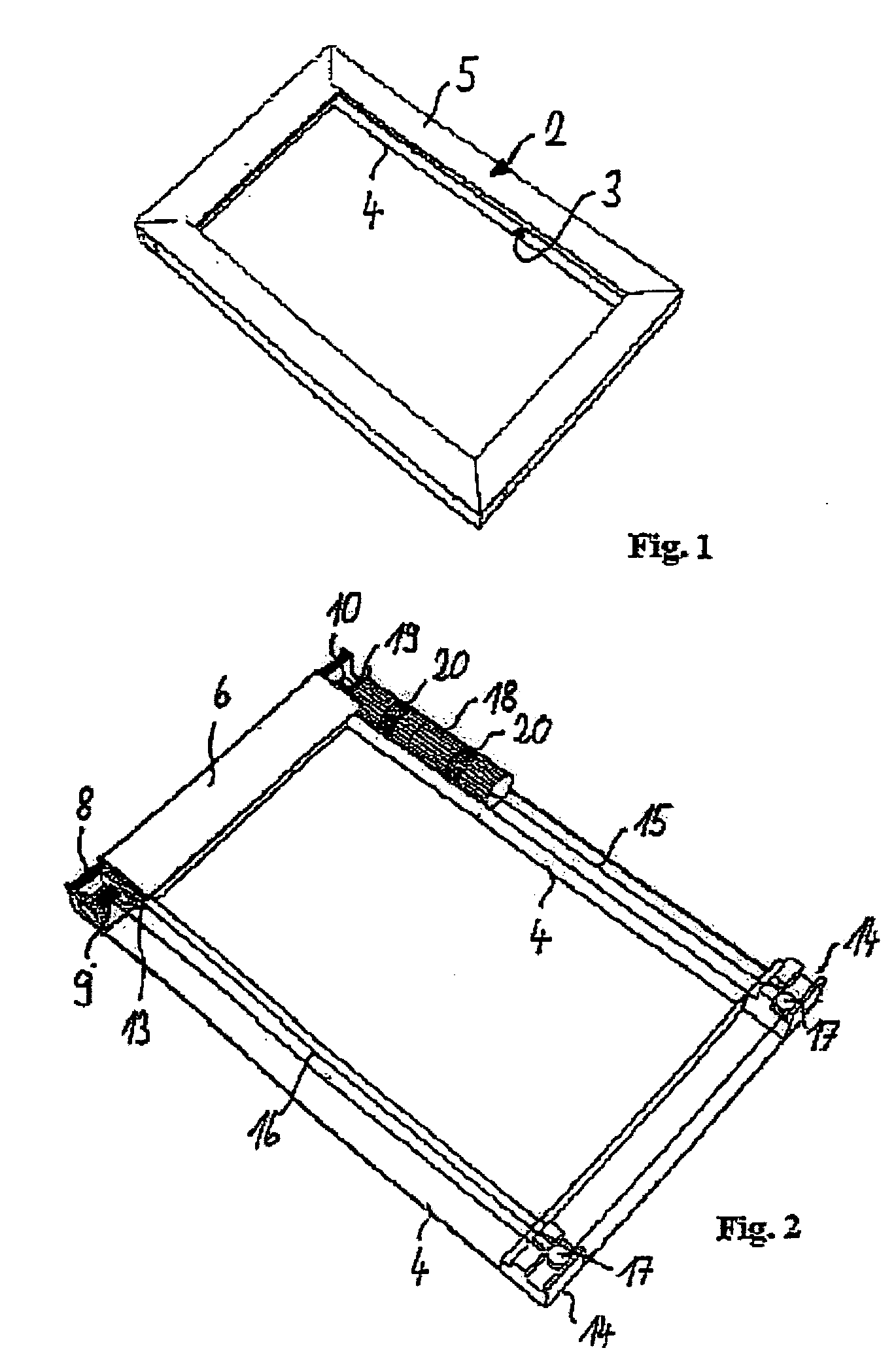
[0027]FIG. 1 shows a frame 2 into which a roller blind device in accordance with the invention is integrated. Frame 2 consists of lower frame part 4 and upper frame part 5. Furthermore, guide slot 3 can be recognized. Frame 2 preferably consists of sheet-metal profiles or plastic profiles formed in such a manner that after assembly they enclose the mechanism, shown in the following in detail. Guide slot 3, in which the fabric and the pull rod move in a guided fashion, remains on the inside of frame 2.

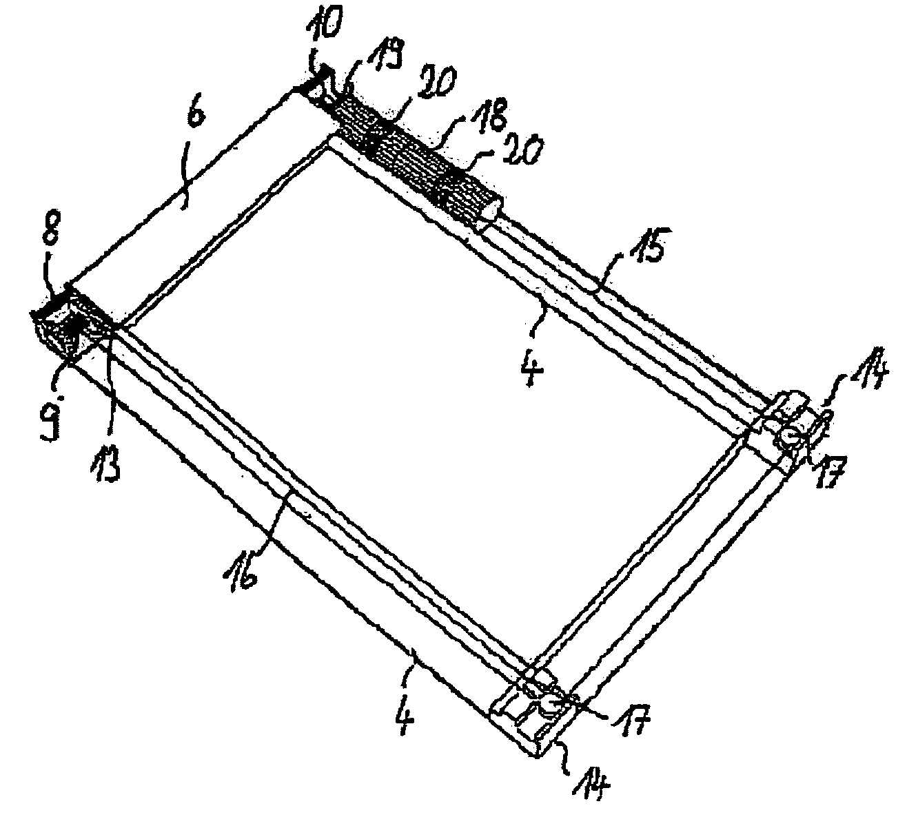
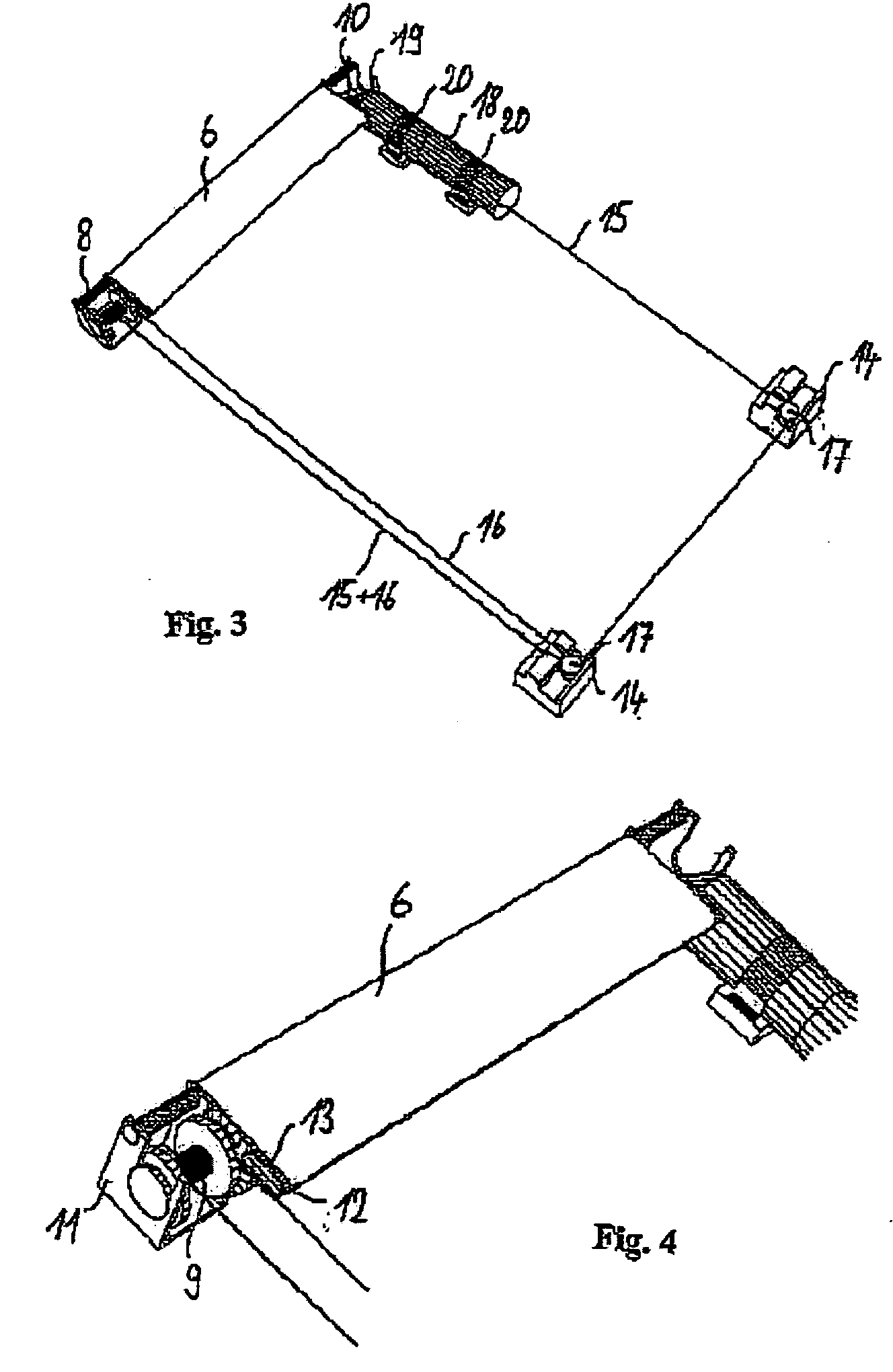
[0028]FIG. 2 shows the arrangement shown in FIG. 1 without upper frame part 5, as a result of which part of the mechanism becomes visible. Fabric 6 used for shading is wound onto a fabric shaft and diverted once over diverter shaft 8. Cord reel 9 and bevel gear 10 are connected to the fabric shaft in such a manner that they rotate in unison with it. The fabric shaft is clipped into clip holders 11 that hold frame parts 4, 5 together at the same time. Pull rod 12 is connected to the end...


PUM


Abstract

A roller blind device including a fabric, which can be wound on a rotationally drivable fabric shaft that is mounted on a frame, and including a pull rod that is placed on the free edge of the fabric. Prior art roller blind devices reduce the window surface area. The aim of the invention is to further develop a prior art roller blind device in order to obtain a simple, inexpensive and compact design that reduces the incidence of light only minimally. To this end, the invention provides that a cord reel is connected to the fabric shaft in a rotationally fixed manner while being coaxial to said fabric shaft and located in the extension thereof, and the free end of the cord that can be wound on the reel is connected to the pull rod via a cord diverter. When the fabric is pulled from the fabric shaft, the cord is wound on the cord reel and vice versa. A spring device is provided over the course of the cord in order to adapt the cord to the varying winding state of the fabric shaft and cord reel.

Description

CROSS-REFERENCES TO RELATED APPLICATIONS [0001] This application is a continuation of International Application No. PCT / EP2003 / 005383, filed May 23, 2003, the contents of which are here incorporated by reference in their entirety. The benefits of 35 USC Section 120 are here claimed.TECHNICAL FIELD [0002] The invention relates to a roller blind device as well as to a pane of insulating glass provided with such a roller blind device and to a correspondingly equipped window. BACKGROUND OF THE INVENTION [0003] The simplest kind of such roller blind devices are, e.g., the known bolt spring rollers or snap rollers. In these devices a torsional spring is arranged in the fabric shaft and an engagement mechanism for different roll-off lengths of the fabric is provided. These roller blinds require a significant amount of force for operation and frequently snap upward in an undesired manner. In addition, roller blinds with cord tensioning devices are known. In these instances the cord is rolle...

Claims


Application Information

Patent Timeline
IPC IPC(8): E06B9/42E06B3/32E06B9/62E06B9/68
CPCE06B9/62E06B9/42
Inventor TUSSINGER, PHILIPP
Owner TUSSINGER PHILIPP
Why Eureka
Try Eureka