Signal transmission over a wire pair

a technology of signal transmission and wire pair, which is applied in the direction of cathode-ray tube indicators, television systems, instruments, etc., can solve the problems of increasing the number of users or computers, increasing the complexity and cost of the switching apparatus, and exacerbated problems

Inactive Publication Date: 2005-07-28
ADDER TECHNOLOGY
View PDF5 Cites 28 Cited by
  • Summary
  • Abstract
  • Description
  • Claims
  • Application Information

AI Technical Summary

Benefits of technology

[0016] A colour control signal can be transmitted during the horizontal synchronisation signal period which indicates the colour of the analogue video signal in the next analogue video signal following the horizontal synchronisation signal. The colour control signal can be provided by two bits. Three different combinations of the two bits can indicate three different colours.
[0017] A transmission mode control signal can be transmitted during the horizontal synchronisation signal period which indicates whether the signal following the horizontal synchronisation signal is an analogue video colour signal or a peripheral data signal. The transmission mode control signal can be a bit transmitted on the horizontal synchronisation signal. The transmission mode control signal can be the first of a plurality of bits transmitted on the horizontal synchronisation signal.

Problems solved by technology

However, the use of four twisted pair cable gives rise to a number of problems which are exacerbated as the size of the enterprise system increases.
Hence increasing the number of users or computers increases the complexity and cost of the switching apparatus.
Further, the sheer number of cables and amount of cabling required can cause significant problems.

Method used


Image

  • Signal transmission over a wire pair
  • Signal transmission over a wire pair
  • Signal transmission over a wire pair

Examples


Embodiment Construction

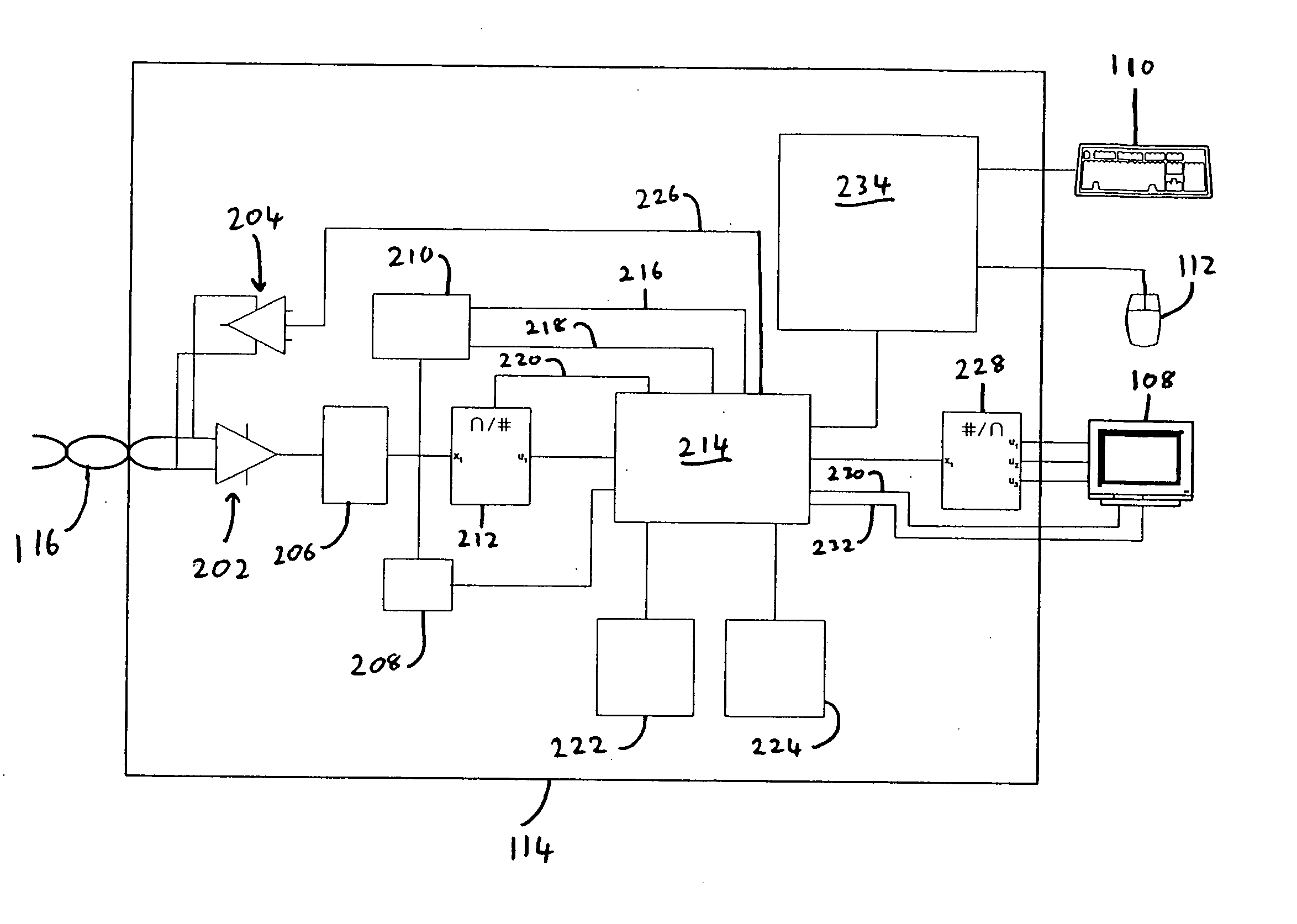
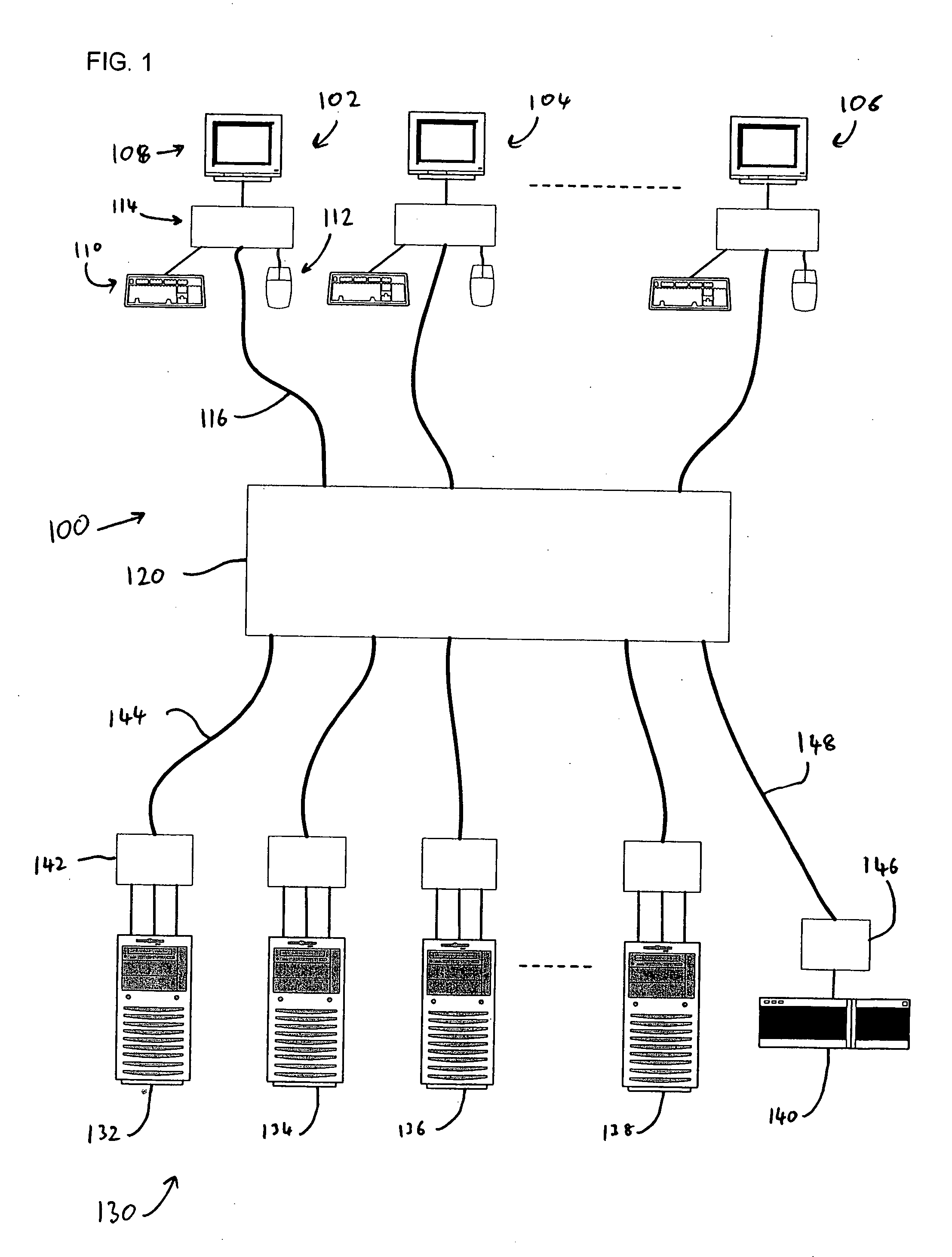
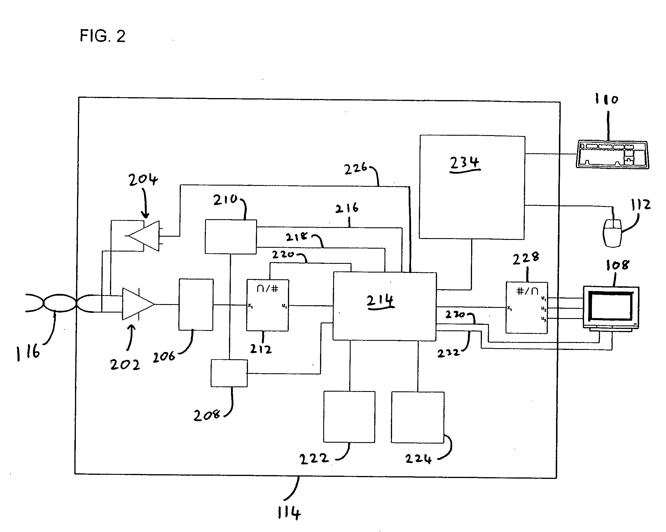
[0042] With reference to FIG. 1 there is shown an Enterprise KVM System 100. The Enterprise System includes a plurality of user stations, although only three, user stations 102, 104 and 106 are shown in FIG. 1. In practice, any number of user stations can be provided as appropriate for the requirements of the system. Each user station includes a video display unit 108, in the form of a computer monitor or similar, a keyboard 110 and a mouse 112. Other pointer devices can be used as part of the user station in place of mouse 112. The user station can also include other peripheral devices, such as audio speakers. Each user station also includes a user station interface device 114 to which the keyboard, mouse and monitor are each connected.

[0043] The Enterprise KVM System 100 also includes a matrix switching unit 120. Each user interface device 114 is connected by a single twisted pair cable 116 to the matrix switching unit 120.

[0044] KVM Enterprise System 100 also includes a plurali...


PUM


Abstract

An enterprise KVM system using single twisted pairs to transmit video and data signals is described together with circuitry for the parts of the system and a method of transmitting the signals. The method transmits a video signal and peripheral data over a single twisted pair between a computer and a plurality of peripherals. A sequence of a plurality of analogue video color signals with a vertical synchronisation signal following each analogue video signal is transmitted from the computer to the plurality of peripherals. Peripheral data is transmitted between the plurality of peripherals and computer during the vertical synchronisation signal transmission periods. The KVM enterprise system comprises a plurality of user stations, each user station including a keyboard, mouse and video display connected to a user interface. A plurality of computers are provided each connected to a dongle and supplying video, keyboard and mouse signals to the dongle. A KVM matrix switch is also included. Each of the dongles is connected to the matrix switch by a respective single twisted pair cable. Each of the user interfaces is connected to the matrix switch by a respective single twisted pair cable. Video signals and keyboard or mouse signals are transmitted via the twisted pair cables between any one of the plurality of computers and any one of the user stations.

Description

BACKGROUND OF THE INVENTION [0001] The present invention relates to transmitting signals over cables between computers and peripherals, and in particular to transmitting video, and preferably peripheral, signals over a single pair of wires. [0002] Keyboard, Video and Mouse (KVM) switches are used to connect a one or more KVM user stations, including a keyboard, video display and mouse to a plurality of computers so that a one or more users can remotely control a selected one of the plurality of computers. KVMA switches can also be provided which support audio also. One scenario in which KVM switches can be used is in enterprise hardware architectures in which a large number of users require access to a large number of computers. For example a typical enterprise solution would be required to have the ability to connect 8 users to 32 computers. Systems allowing 64 users to thousands of computers have been built. [0003] Enterprise KVM systems typically use twisted pair network cable ha...

Claims


Application Information

Patent Timeline
Patent Type & Authority Applications(United States)
IPC IPC(8): G06F3/023G06F3/14H04N7/085H04N7/088H04N7/10H04N11/08
CPCG06F3/023G06F3/14H04N11/08H04N7/088H04N7/108H04N7/085
Inventor DICKENS, NIGEL ANTHONY
Owner ADDER TECHNOLOGY
Why Eureka
Try Eureka