Refrigerant subcooling by condensate

a technology of condensate and refrigerant, applied in the field of vapor compression system, can solve the problems of limiting the further reduction of refrigerant temperature, ineffective, and reducing the driving force of heat rejection, and achieve the effect of facilitating subcooling

Active Publication Date: 2005-08-04
CARRIER CORP
View PDF14 Cites 22 Cited by
  • Summary
  • Abstract
  • Description
  • Claims
  • Application Information

AI Technical Summary

Benefits of technology

[0008] One example system includes a compressor, a condenser, an evaporator an expansion device between the condenser and the evaporator, and refrigerant lines connecting these components. The system further includes a subcooling portion that facilitates subcooling of the refrigerant flowing between the condenser and the expansion device using the condensate that forms on the evaporator.

Problems solved by technology

A drawback of this prior art system is that it is not effective, particularly in high efficiency vapor compression systems having large condenser coils, since the heat rejected in the condenser is still limited by the outdoor air temperature.
Thus, the driving force for the heat rejection diminishes, establishing a limit for further refrigerant temperature reduction.

Method used


Image

  • Refrigerant subcooling by condensate
  • Refrigerant subcooling by condensate
  • Refrigerant subcooling by condensate

Examples


Embodiment Construction

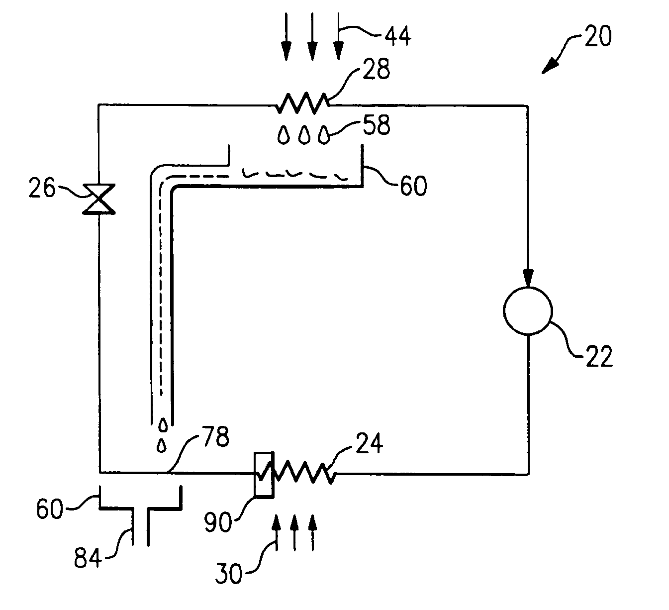
[0022]FIG. 1 illustrates an example vapor compression system 20 including a compressor 22, a condenser 24, an expansion device 26, and an evaporator 28. The refrigerant exits the compressor 22 at a high pressure and a high enthalpy. The refrigerant then flows through the condenser 24 at a high pressure. An external fluid medium 30, such as water or air, also flows through the condenser 24 and exchanges heat with the refrigerant flowing through the condenser 24. In the condenser 24, the refrigerant rejects heat into the external fluid medium 30, and the refrigerant exits the condenser 24 at a relatively low enthalpy and a high pressure.

[0023] The refrigerant then passes through the expansion device 26, which expands the refrigerant, reducing its pressure and temperature. The expansion device 26 can be a mechanical expansion device (TXV), an electronic expansion valve (EXV) or other type of known expansion device.

[0024] After expansion, the refrigerant flows through the evaporator 2...


PUM


Abstract

Refrigerant is circulated through a vapor compression system including a compressor, a condenser, an expansion device, and an evaporator. Cold condensate forms on the evaporator surfaces as the refrigerant accepts heat from an air stream. The cold condensate drips down from the evaporator coil and collects in a condensate pan. In one example, the cold condensate is directed into a condensate heat exchanger to subcool the refrigerant exiting the condenser. In another example, the refrigerant exiting the condenser flows through a refrigerant line located in the condensate pan. In another example, the cold condensate is sprayed on the refrigerant line exiting the condenser or on the subcooling portion of the condenser. By utilizing the condensate for further subcooling of the refrigerant, system capacity and efficiency are enhanced. Various control techniques and condensate flow methods are also disclosed.

Description

BACKGROUND OF THE INVENTION [0001] The present invention relates generally to a vapor compression system that uses the cold condensate from an evaporator to further subcool refrigerant exiting the condenser to increase system capacity and efficiency. [0002] In a vapor compression system, refrigerant is compressed to a high pressure in a compressor. The refrigerant then flows through a condenser and rejects heat to a secondary fluid medium. The high pressure and relatively low enthalpy refrigerant is then expanded in an expansion device. The refrigerant then passes through an evaporator and accepts heat from another secondary fluid medium, such as air. The relatively high enthalpy and low pressure refrigerant then reenters the compressor, completing the cycle. [0003] When refrigerant flows through the evaporator, moisture is removed from the air stream, and cold condensate forms on the surface of the evaporator coil. The cold condensate typically drips from the evaporator surface int...

Claims


Application Information

Patent Timeline
Patent Type & Authority Applications(United States)
IPC IPC(8): F24F13/22F25B40/02F25D21/14
CPCF24F2013/225F25D21/14F25B40/02
Inventor DOBMEIER, THOMAS J.TARAS, MICHAEL F.LIFSON, ALEXANDER
Owner CARRIER CORP
Why Eureka
Try Eureka