Friction stir rivet drive system and stir riveting methods

a technology of friction plunge riveting and drive system, which is applied in the direction of manufacturing tools, soldering devices, auxillary welding devices, etc., can solve the problems that the prior friction-stir fastening does not meet new requirements, and achieves faster and more accurate friction plunge riveting, improved rivet drive, and reduced scrap.

Inactive Publication Date: 2005-08-18
GM GLOBAL TECH OPERATIONS LLC
View PDF3 Cites 76 Cited by
  • Summary
  • Abstract
  • Description
  • Claims
  • Application Information

AI Technical Summary

Benefits of technology

[0008] Improved rivet drive with faster and more accurate friction plunge riveting with minimized lost parts and scrap are provided by this invention. With this invention a wide range of stir rivet head designs can be readily utilized including those with elongated drive slots or upstanding polygonal protuberances in or on the heads to share input torque for improved stir riveting and to reduce or eliminate metal deformation in the head that might otherwise occur during high torque installations.

Problems solved by technology

Prior friction-stir fastening do not meet new and higher standards and objectives for machines and methods providing optimal high production rates that feature consistent superior quality friction-stir fastening and joining of parts.

Method used


Image

  • Friction stir rivet drive system and stir riveting methods
  • Friction stir rivet drive system and stir riveting methods
  • Friction stir rivet drive system and stir riveting methods

Examples


Embodiment Construction

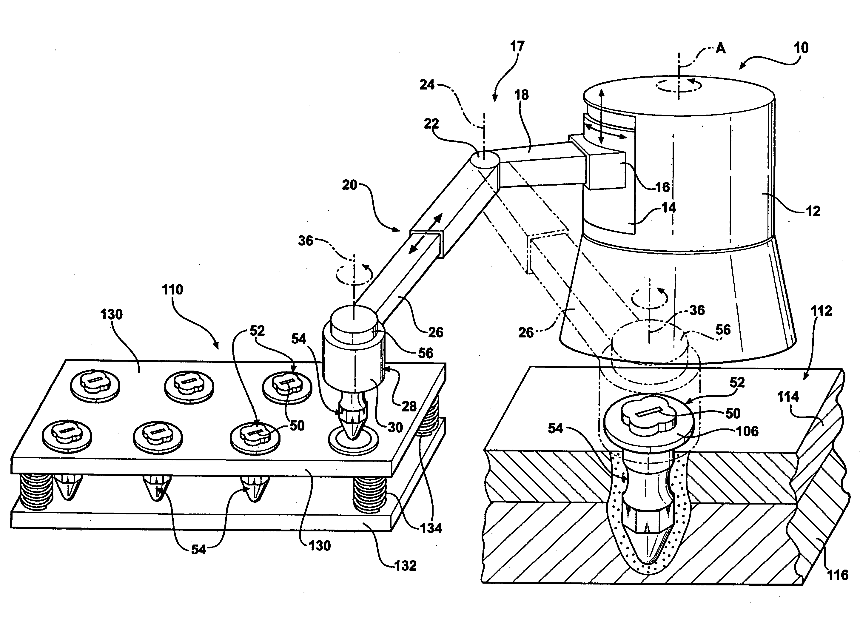
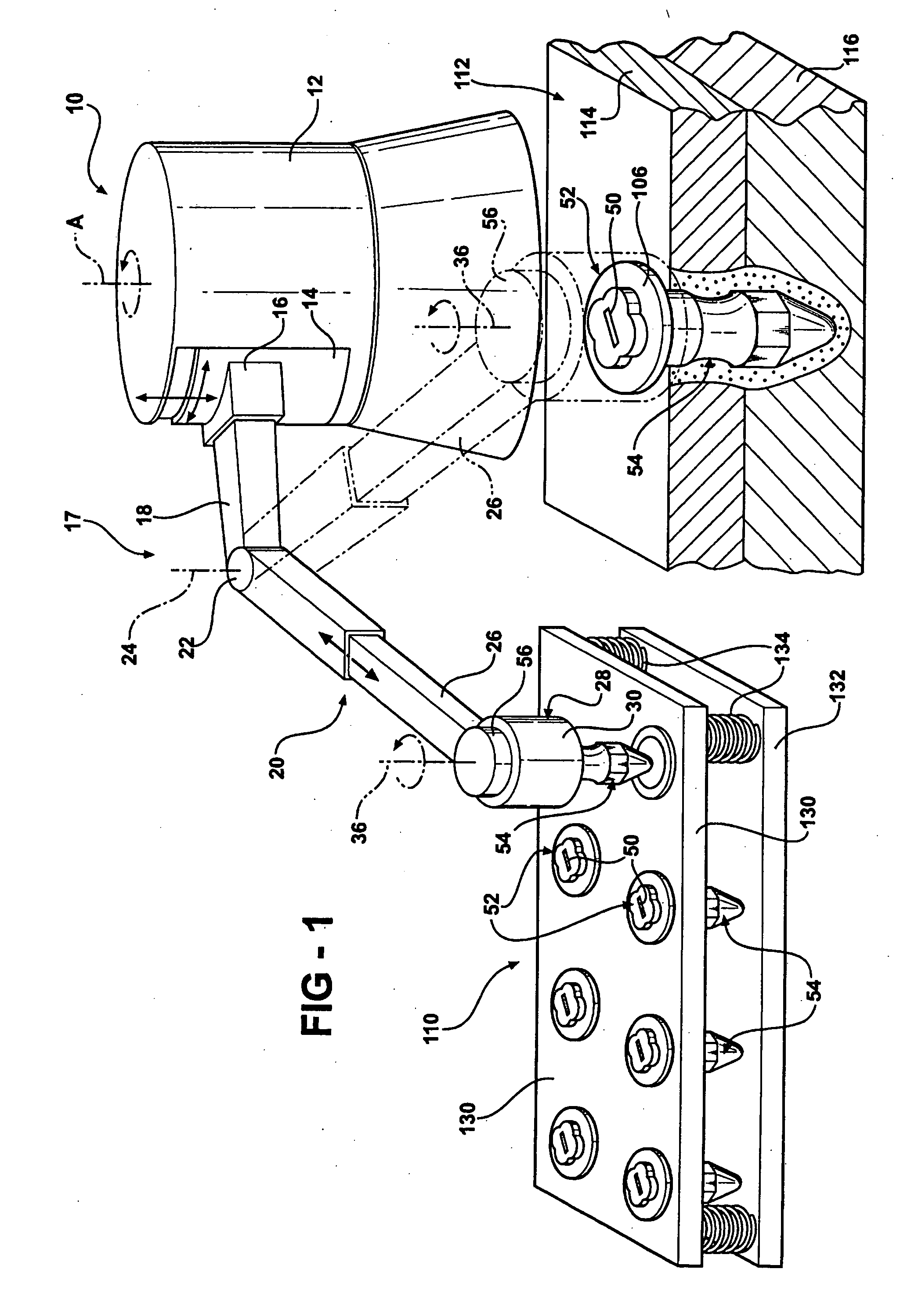
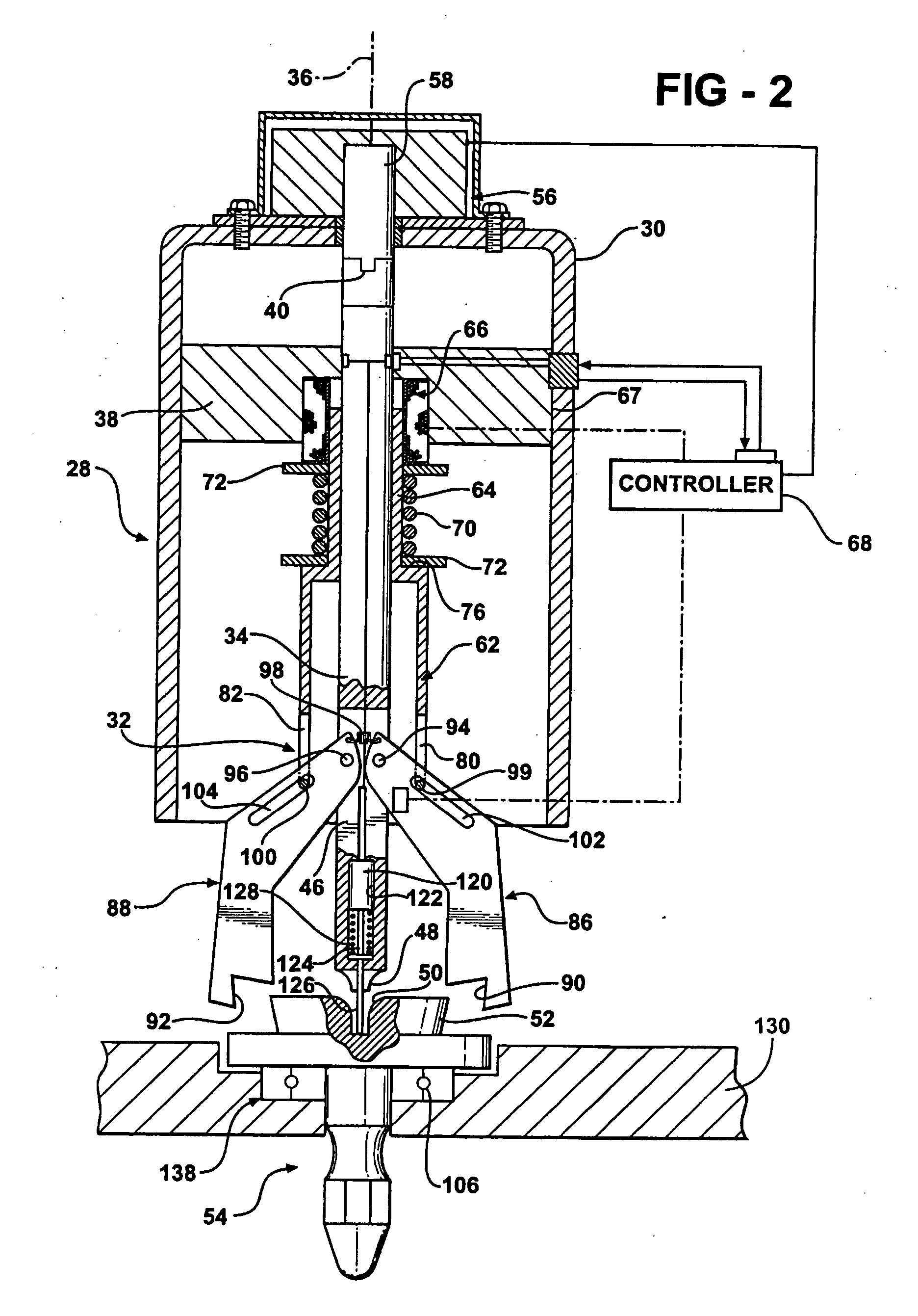
[0019] Turning now in greater detail to the drawings there is diagrammatically illustrated in FIG. 1, a manufacturing robot 10 having a main housing structure 12 that is provided with an inner rotor 14 computer controlled and powered for vertical and rotary motion with respect to axis A. The rotor 14 has a radially projecting shoulder 16 that operatively mounts a robot arm 17. The computer controlled robot arm is movable with precision and to an infinite number of programmed positions and comprises a support arm 18 to which a forearm 20 is operatively connected by pivot unit 22 for turning movement about vertical axis 24 thereof. The forearm 20 has a telescopic extension 26 that terminates in a working head 28 having a generally cylindrical housing 30 with a powered fastener gripping jaw unit 32 (FIG. 2) rotatably mounted therein.

[0020]FIG. 2 diagrammatically illustrates the gripping jaw unit 32, comprising an elongated drive shaft 34 operatively mounted for rotation about a centra...


PUM

PropertyMeasurementUnit
rotational speedaaaaaaaaaa
frictionaaaaaaaaaa
torqueaaaaaaaaaa

Abstract

Friction stir fastener equipment and method in which a series of friction stir rivets are rotatably mounted in a supply station and a computer controlled arm terminating in a rotating working head having special gripping jaws that precisely locates and grips a selected rivet. The arm then moves the rotating rivet and progressively drives it into the work until a frictionally heated and plasticized zone of material around the shank of the rivet begins to solidify. The jaws then release the rivet from the drive so that the rivet rotation decelerates to zero. Sufficient hardening of the zone effects the completion of one stir riveting cycle which may be automatically repeated.

Description

TECHNICAL FIELD [0001] This invention generally relates to friction stir riveting and more particularly to new and improved friction stir rivet gripping, pickup and drive systems and stir riveting methods. In this invention a rotating driver locates and selectively picks up a friction stir rivet from a carrier and transfers it to a work station and then rotatably drives the rivet into layered work at predetermined rotational speeds and loads to connect the work by friction stir riveting. BACKGROUND OF THE INVENTION [0002] Friction welding is a known process for joining and repairing parts such as those of iron, aluminum or other suitable metals as well as many plastic materials utilizing the heat of friction to plasticize the interface of relatively rotating components and then allowing the interface to cool and fuse so that the components are metallurgically integrated and securely joined together. In one aspect of friction welding, frequently referenced as friction stir welding, a...

Claims


Application Information

Patent Timeline
Patent Type & Authority Applications(United States)
IPC IPC(8): B21J15/12B23H9/00B23K20/12
CPCB21J15/027B23K20/127B23K20/1245B23H9/00B25J15/0226
Inventor STEVENSON, ROBINWANG, PEI-CHUNG
Owner GM GLOBAL TECH OPERATIONS LLC
Why Eureka
Try Eureka