Frequency division method and device

Inactive Publication Date: 2005-08-18
THALES SA
View PDF8 Cites 18 Cited by
  • Summary
  • Abstract
  • Description
  • Claims
  • Application Information

AI Technical Summary

Benefits of technology

[0040] N may vary dynamically by a value ΔN while at the same time controlling the duration of one of the two states of the output signal. This makes it possible to meet the requirement arisin

Problems solved by technology

Such a structure has especially the following drawbacks: The counters 2 and 3 are synchronous counters for which all the stages must work at a high frequency equal to Fe/Na, T

Method used


Image

  • Frequency division method and device
  • Frequency division method and device
  • Frequency division method and device

Examples


Embodiment Construction

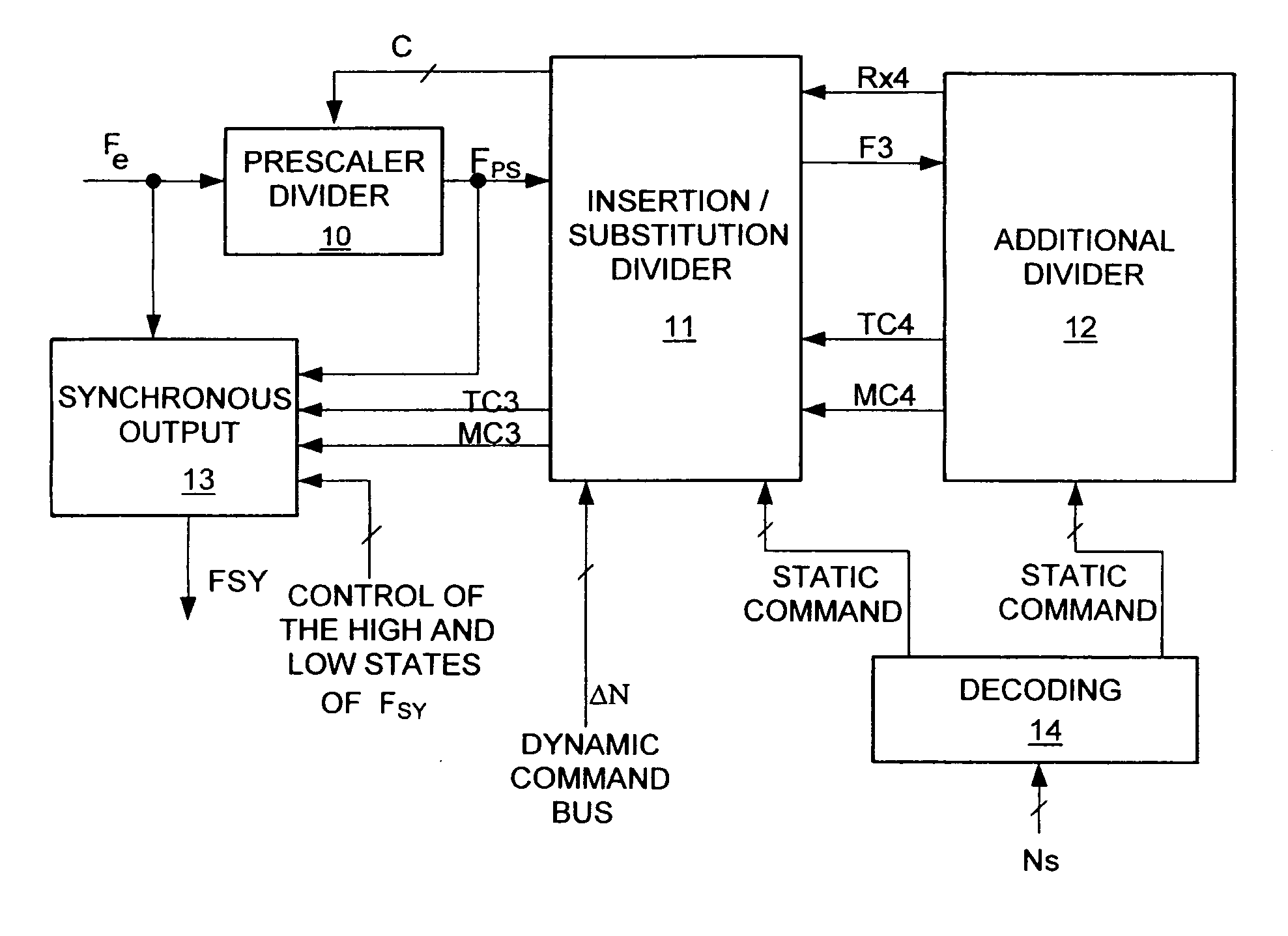
[0054]FIG. 4 exemplifies an architecture of a frequency divider according to the invention formed, for example, by five blocks. [0055] an input divider block placed at the front-end of the division chain or prescaler divider 10[0056] an insertion / substitution divider block 11[0057] an additional divider block 12[0058] a synchronous output block 13[0059] a decoding block 14.

[0060] The set works in the manner described here below. The blocks and their function are themselves described in detail. The division ratio N of the set thus formed is defined as N=Ns+ΔN where Ns is the static part of N and ΔN is the requested variation.

[0061] The input signal Fe is divided by the value of the division ratio Nps of the input divider 10 which delivers the signal Fps to the insertion / substitution divider 11. Nps may take, for example, all the values in an octave from A to 2A, in response to a bus of commands C coming from the insertion / substitution divider 11.

[0062] The insertion / substitution d...


PUM


Abstract

A method and device of frequency division with a division ratio: comprising: an input divider with a division ratio NPs receiving the frequency Fe at input and delivering a signal to an insertion/substitution divider, the insertion/substitution divider having an input of variation of the division ratio, delivering a command frame to the input divider and generating an end-of-count signal, the insertion/substitution divider being adapted to the insertion of one or more input divider cycles and/or the substitution of an input divider cycle in the command frame.

Description

BACKGROUND OF THE INVENTION [0001] 1. Field of the Invention [0002] The invention relates to a frequency divider. [0003] It can be applied, for example, to the field of frequency synthesis where the phase noise of the divider is a key performance characteristic. [0004] In its general principle, a frequency divider with a division ratio N enables the output generation of a signal with a duration N*Te where Te is the period of the input signal of the divider. The output signal with a duration N*Te is generally constituted by only one high state and only one low state [0005] When a divider is placed in a phase-locked loop, the static modification, in steps of one, of the N division ratio generates frequency steps at output of the loop. These steps are spaced out by the value of the comparison frequency of the loop. It is possible to generate frequency steps which are a fraction of this comparison frequency by using the divider in fractional mode. In this mode, after statically setting ...

Claims


Application Information

Patent Timeline
IPC IPC(8): G06F7/68H03K23/50H03K23/66H03K23/68
CPCH03K23/68G06F7/68
Inventor DE GOUY, JEAN-LUCGABET, PASCAL
Owner THALES SA
Why Eureka
Try Eureka