Retractable cable winder

a winder and cable technology, applied in the field of cable winders, can solve the problems of cable damage, axial twist created, and the damage of the cable is greater, and achieve the effect of eliminating any damage to the optical fiber and simple action

Inactive Publication Date: 2005-08-25
COMSTAR COMM
View PDF2 Cites 113 Cited by
  • Summary
  • Abstract
  • Description
  • Claims
  • Application Information

AI Technical Summary

Benefits of technology

[0008] The present invention provides a retractable cable winder which enables a paid-out length of a retractable cable to be extended from the winder without the need to also extend the other stationary end of the cable. The design of the winder according to the present invention enables the stationary end of the cable to curl up inside the buffer compartment of the winder. As the retractable end extends, the upper and lower track reels, which store the retractable cable, also turns. Since the stationary cable is a continuation of the retractable cable, the turning force of the track reel compels the stationary cable to turn in an opposite direction within the circular buffer compartment. Since the buffer compartment is relatively large, the stationary cable simply starts to curl up and slowly tightens around the buffer reel seat located at the center of the buffer reel. After use, as the retractable cable is being retracted and winded up inside the winder, the stationary cable within the buffer compartment will turn in the opposite direction and becomes loosely curling around the reel seat. Thus, the winder of the present invention enables the user to extend and to retract a predetermined length of a cable by simple actions, with relative ease and without the need to use any tool.
[0009] It is a principal object of the invention to provide an improved cable winder which only extends one end of the cable and still preserves the physical properties of the cable. In the case of optical fiber cables, the construction and operation of the improved cable winder eliminates any damages to the optical fiber created by axial tw

Problems solved by technology

However, a major problem with the conventional cable winders is the axial twist created by the winding action of the stored cable along the rotational axis of the winder case.
This axial twist often results in cable damage since for every turn of winding the cable, it twists the centre core 360°.
The more turns the cable winds, the greater the damage is resulted from the axial twist.
While ordinary electrical cables may be able to sustain some extents of twisting, it will create unmanageable damages to optical fibre cables due to the inherent physical properties of these cables which limit the bending radius of the optical fibre within the cable.
Such traditional double exten

Method used


Image

  • Retractable cable winder
  • Retractable cable winder
  • Retractable cable winder

Examples


example

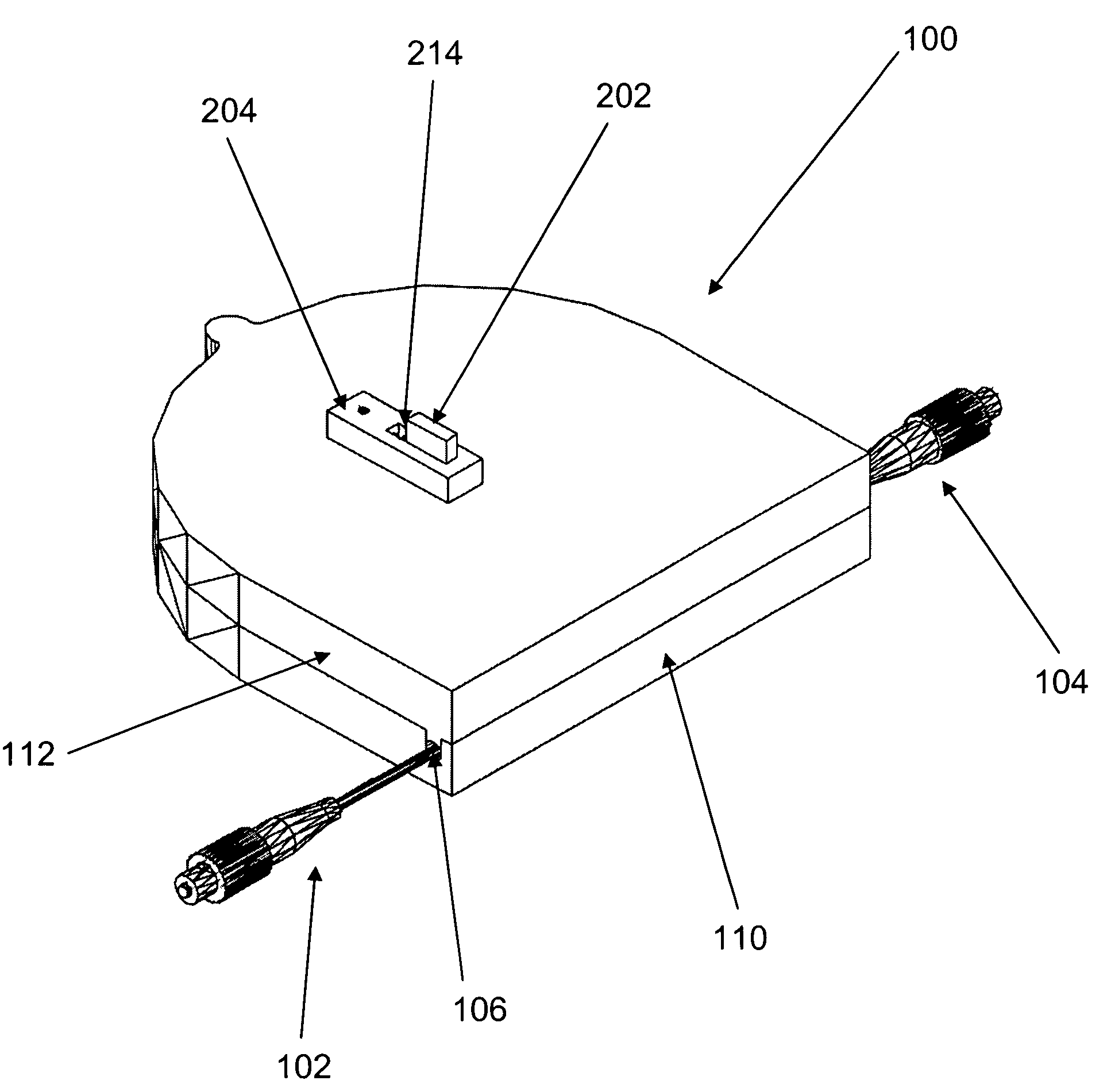
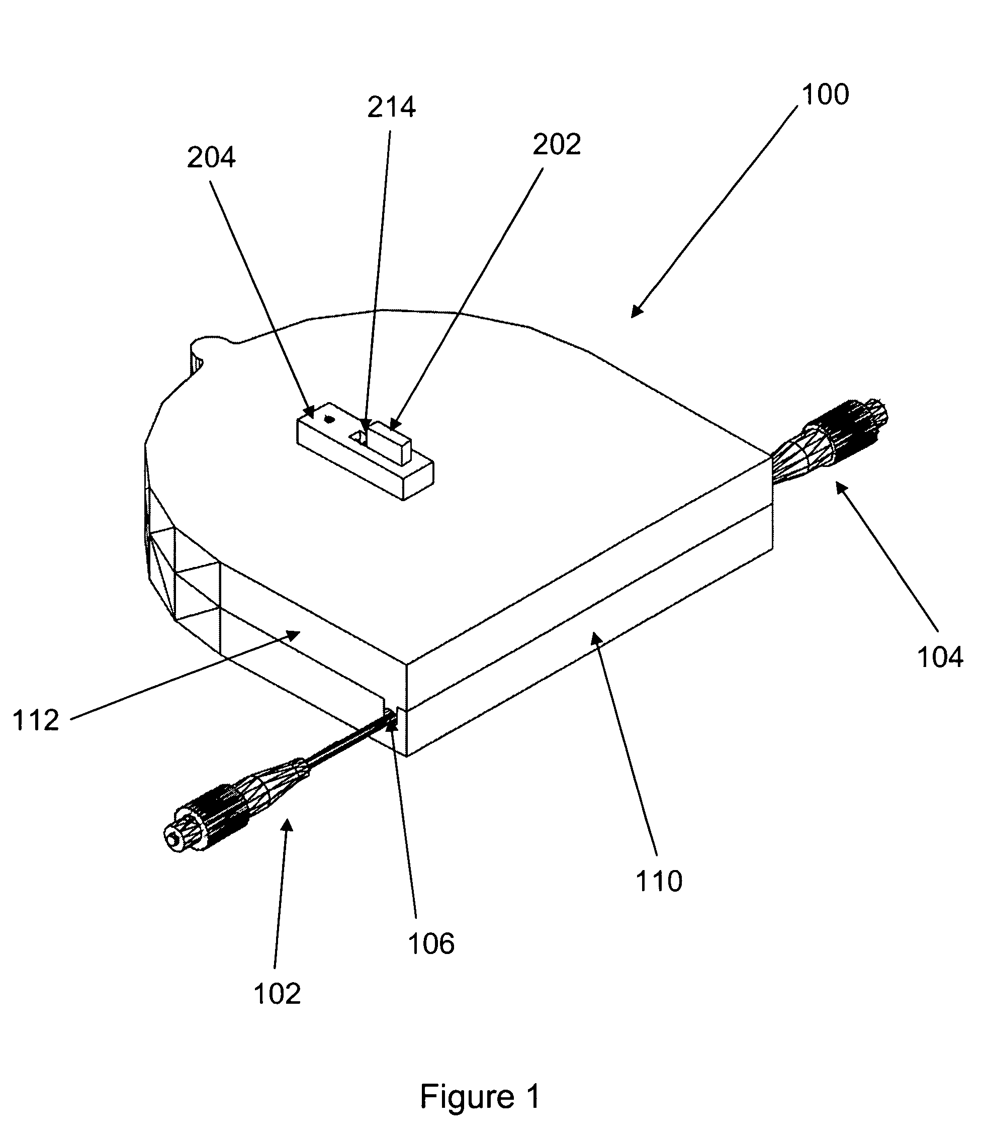
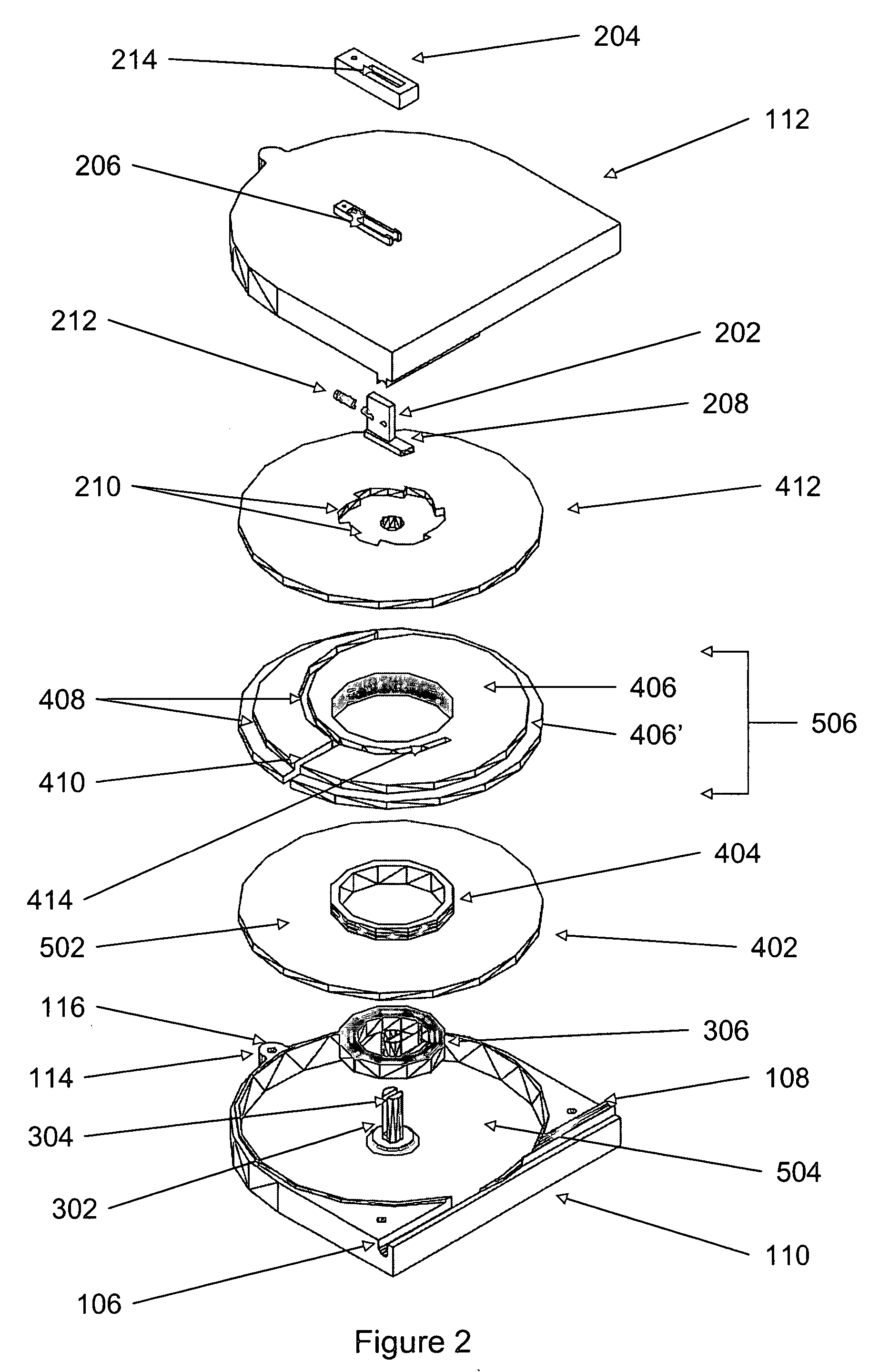
[0039] Assume the value of E, F, G, and L3 is 0.09, 0.08, 0.06 and 0.11 respectively, if the user wants to know the Efficiency of Cable for 1 m retractable cable, by equation (4) the user gets 2.67. The total cable length is 1+2.67+0.11=3.78 m. i.e. The Efficiency of Cable for the winder is 0.26. The cable winder of the present invention further comprises a ratchet reel 412 for locking and communicating with the spring-urged pawl lock button 202. Ratchet reel 412 is located immediately above the upper spiral track reel 406 and is operatively engaged to the coil-spring 306.

[0040] The locking and releasing mechanisms of the present invention consist of a pawl spring 212 urging against the pawl lock button 202, which has a pawl spring lock arm 208 attached thereunder (see FIG. 2). As the retractable cable 104 extends and the ratchet reel 412 rotates, the urging force exerted by the pawl spring 212 pushes the pawl spring lock arm 208 forward and engages one of the many ratchet reel tee...


PUM


Abstract

A cable winder is disclosed. The winder takes into consideration the minimum-bending radius of the optical fiber cables and minimizes cable attenuation when optical fiber cables are being stored. The winder allows only one end of the cable to be extended and rewind, while the other end of the cable, which operatively connects to the retractable cable, remains stored inside the cable winder without being damaged by the axial twist resulted from the winding action of the retractable cable. The winder enables a user to pre-determine the dimension of cable length and cable efficiency in order to maximize operation effectiveness.

Description

FIELD OF THE INVENTION [0001] This invention relates to a cable winder which allows only the retractable end of a cable to be released and winded up while the other end of the cable remains stored inside the cable winder without being damaged by the winding action of the cable which commonly occurs due to axial twisting on the cable. The invention can be also used for optical fiber cables, as well as non-optical fiber cables, such as cooper or steel or other wires and cables. BACKGROUND OF THE INVENTION [0002] Cable winders are quite common amongst cable users for storing telephone or other utility cords. By using a cable winder, the user avoids the messy twisting, kinking, crinkling and coiling up of extended cables. However, a major problem with the conventional cable winders is the axial twist created by the winding action of the stored cable along the rotational axis of the winder case. This axial twist often results in cable damage since for every turn of winding the cable, it ...

Claims


Application Information

Patent Timeline
IPC IPC(8): B65H75/34B65H75/40B65H75/44B65H75/48G02B6/44H02G11/02H04M1/15
CPCB65H75/4431G02B6/4457B65H2701/32B65H75/4449A43C11/165
Inventor TSOI, CHUNG HAAPCHAN, FREDERICK YING-SHU
Owner COMSTAR COMM
Why Eureka
Try Eureka