Constrained dynamic inversion control algorithm

Active Publication Date: 2005-04-19
RAYTHEON TECH CORP
View PDF8 Cites 39 Cited by
  • Summary
  • Abstract
  • Description
  • Claims
  • Application Information

AI Technical Summary

Benefits of technology

[0005]The present invention provides an improved system and method for controlling a multivariable system using dynamic inversion that observes physical constraints. Because the physical constraints are brought into the dynamic inversion process, the present i

Problems solved by technology

Non-nominal behavior is thus due to, the inevitable, modeling errors.
If it becomes apparent the mo

Method used


Image

  • Constrained dynamic inversion control algorithm
  • Constrained dynamic inversion control algorithm
  • Constrained dynamic inversion control algorithm

Examples


Example

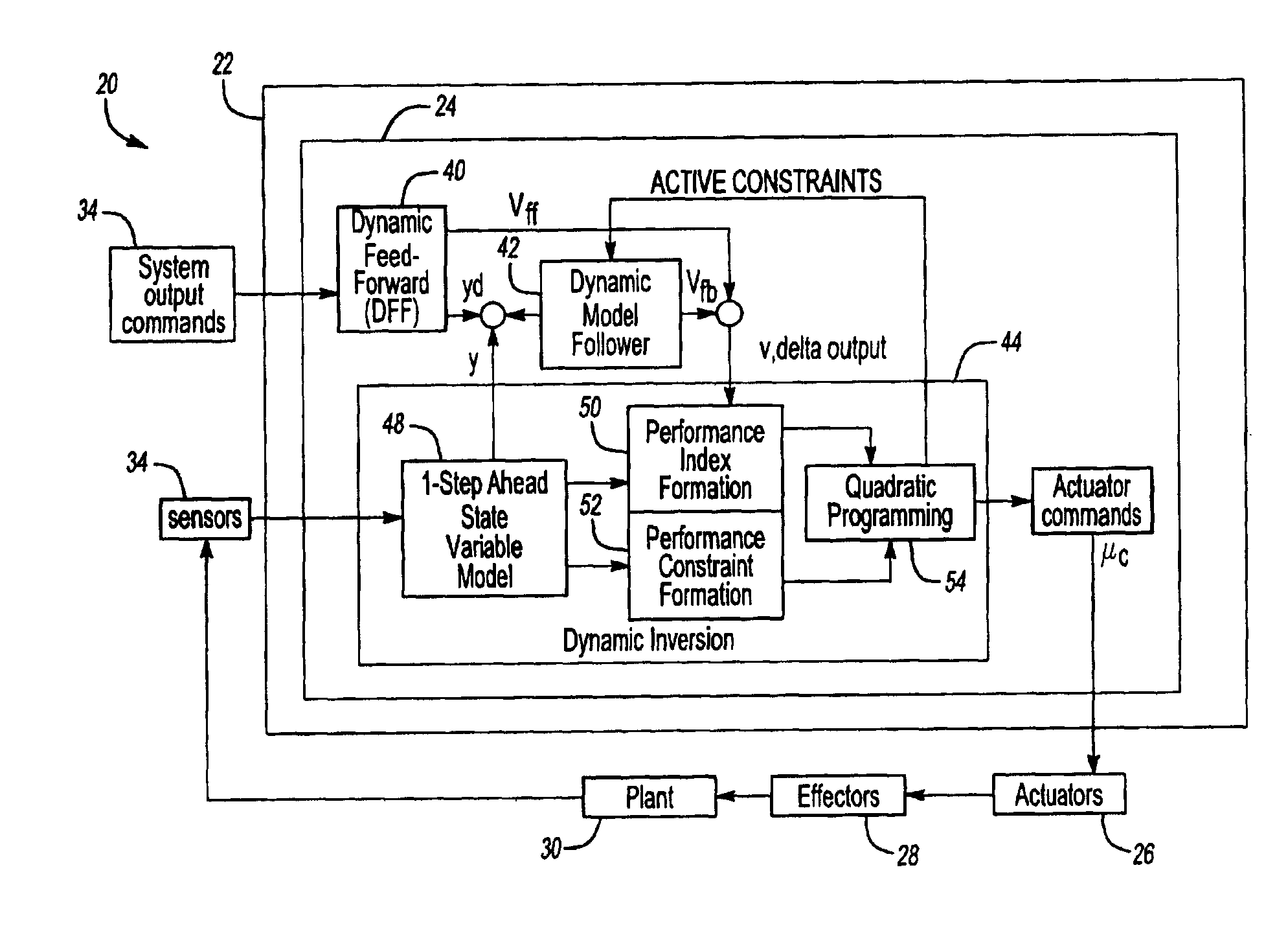
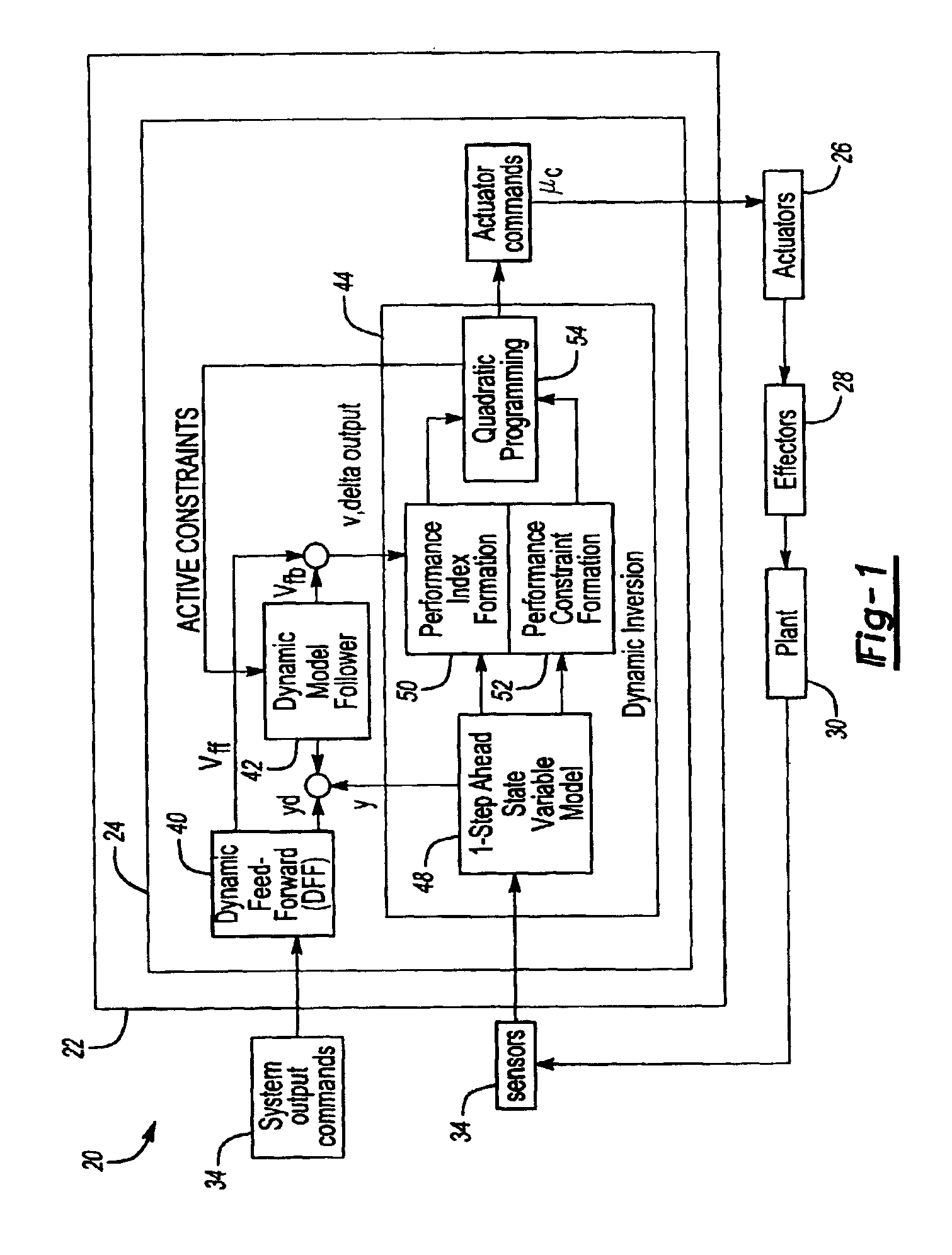
[0013]FIG. 1 illustrates a control system 20 according to the present invention. The constrained dynamic inversion algorithm is meant to be implemented on a discrete time sampled-data computer 22 in order to control a dynamic system. The computer 22 includes a CPU, memory 24 and other known hardware and is programmed to perform as described herein to produce actuator commands, uc. The actuator commands, uc, control a plurality of actuators 26, which take the electronic commands, uc, and turn them into physical forces that adjust a plurality of effectors 28, each of the plurality of actuators 26 being associated with one of the plurality of effectors 28. The effectors 28 change the dynamics of the plant 30. A plurality of sensors 32 provide feedback y to the computer 22. The computer 22 determines the next set of actuator commands, uc, based upon the information from the sensors 32 and based upon system output commands 34, which may come from a human operator or a higher level contro...


PUM


Abstract

A method of controlling a multivariable system includes the step of receiving a plurality of sensor signals indicating current conditions of the system and receiving a plurality of commands. The desired dynamic response of the system is then determined based upon the commands and the sensor signals. The problem of controlling the system to achieve the desired dynamic response without violating numerous actuator and physical constraints is then formulated as a quadratic programming problem. By solving the quadratic programming problem, the effector commands are determined and the physical constraints are enforced.

Description

[0001]This invention was conceived in performance of work under U.S. Government Contract N00421-01-2-0131.BACKGROUND OF THE INVENTION[0002]The present invention relates generally to control systems and more particularly to dynamic inversion control systems.[0003]Dynamic inversion is a method for the design and implementation of control software for realtime, onboard control system computers. A version has been developed by aerospace companies for flight control software for fighter aircraft. Controlling an aircraft's trajectory through the air requires means or effectors (such as the elevator) that can change the aircrafts pitch, yaw, roll, and speed. The main focus of the current versions of dynamic inversion has been control logic for commanding a surplus of means for producing the various forces and moments required. The term surplus implies there are several combinations of effectors, such as thrust vectoring, elevators and canards, that cause the aircraft to pitch, or to yaw, e...

Claims


Application Information

Patent Timeline
IPC IPC(8): G05B13/04G05B11/32G05B13/02
CPCG05B13/042
Inventor FULLER, JAMES W.DAS, INDRANEEL
Owner RAYTHEON TECH CORP
Why Eureka
Try Eureka