Spring clamp electrical terminal

a technology of electrical terminals and springs, applied in the direction of contact members penetrating/cutting insulation/cable strands, electrical apparatus, fastening/insulating connecting parts, etc., can solve the problems of no longer guaranteed reliable contact with electrical conductors, no longer functionally important, and danger of clamping spring slippag

Active Publication Date: 2007-07-03
PHOENIX CONTACT GMBH & CO KG
View PDF11 Cites 42 Cited by
  • Summary
  • Abstract
  • Description
  • Claims
  • Application Information

AI Technical Summary

Benefits of technology

[0013]A primary object of this invention is to provide an electrical supply or connecting terminal of the initially described type which enables simple, but secure fixing of the clamping spring at a size as small as possible even with larger cross sections of the conductor to be connected.
[0019]The metal part is thus similar, first of all, to the conductor rail piece known from European Patent Application EP 1 391 965 A1 and corresponding U.S. Pat. No. 6,814,608. However, in contrast to this known conductor rail piece, in the current bar there is no material passage with a perforated collar inside wall which extends in the insertion direction of the electrical conductor to be connected, but the mounting section is punched out of the current bar and bent down opposite the insertion direction of the electrical conductor to be connected. The clamping spring is seated with its contact leg on the current bar such that the recess in the contact leg and the recess in the current bar are aligned with one another, and the mounting section of the current bar projects through the recess in the contact leg in a direction opposite the insertion direction of the electrical conductor to be connected. In this way, fixing of the clamping spring on the current bar is possible.
[0022]According to a preferred configuration of the electrical supply or connecting terminal of the invention, on the end of the recess away from the end of the clamping leg, a retaining section is punched out of the contact leg of the clamping spring and is bent down in the insertion direction of the electrical conductor to be connected. The retaining section which is bent down essentially perpendicular to the contact leg is used to better fix the clamping spring on the metal part. Depending on the execution of the metal part, the retaining section extends either through the recess in the current bar or the retaining section extends behind the mounting section of the metal part. The execution of the retaining section especially prevents twisting of the clamping spring when the electrical conductor is inserted.
[0023]According to another advantageous embodiment of the invention, the mounting section of the metal part is bent down such that the mounting section, together with the end of the clamping leg of the clamping spring, form an inlet funnel for the electrical conductor to be connected. The execution of the inlet funnel thus automatically correctly positions the tip of an electrical conductor which has been pushed through the conductor inlet opening into the insulating housing so that simple and exact connection of the electrical conductor to the electrical supply or connecting terminal is possible.
[0025]The kink made on the clamping leg enables simpler action of the tip of the actuating tool on the clamping leg for opening the clamping spring. Moreover, in this way, the insertion depth of the actuating tool which is necessary for complete opening of the clamping spring into the actuating opening can be reduced.

Problems solved by technology

Whether in the individual case there is a terminal means or a connecting means, is functionally relatively unimportant.
When the clamping spring is opened, there is the danger that the clamping spring will slip or with the ends of its spring leg will even slip out of the opening so that proper positioning of the clamping spring, and thus, reliable contact-making of the electrical conductor, are no longer guaranteed under certain circumstances when an electrical conductor is being inserted.
It is common to all these known supply terminals that the clamping spring is inserted in an opening of the metal part so that, when the clamping spring is opened, there is the danger that the clamping spring will slip.

Method used


Image

  • Spring clamp electrical terminal
  • Spring clamp electrical terminal
  • Spring clamp electrical terminal

Examples


Embodiment Construction

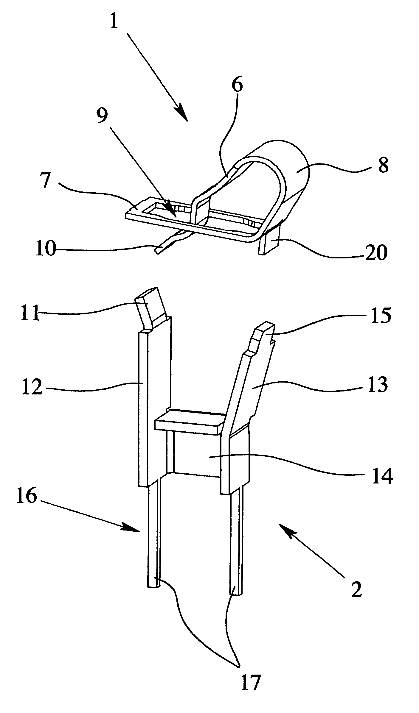
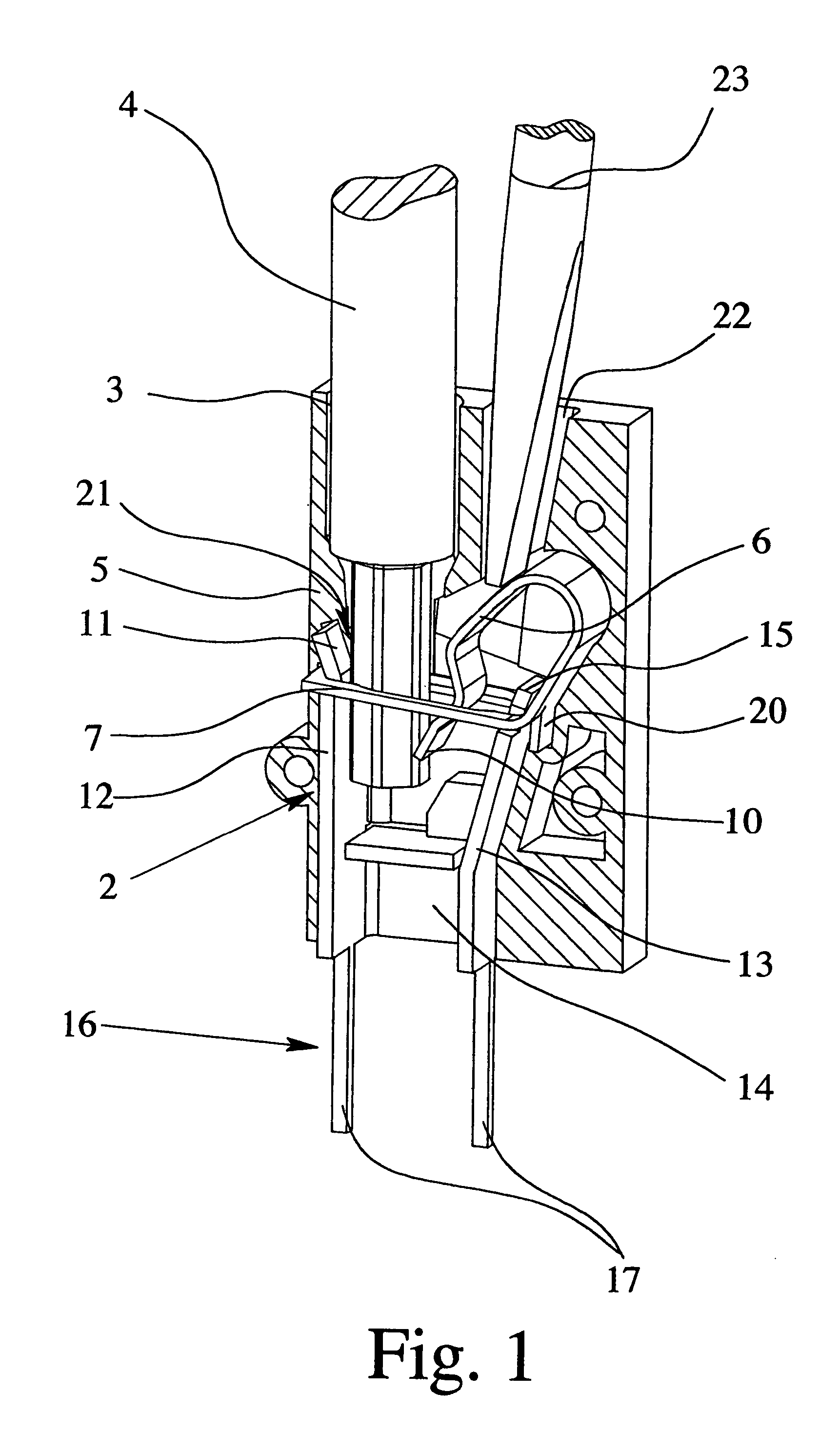
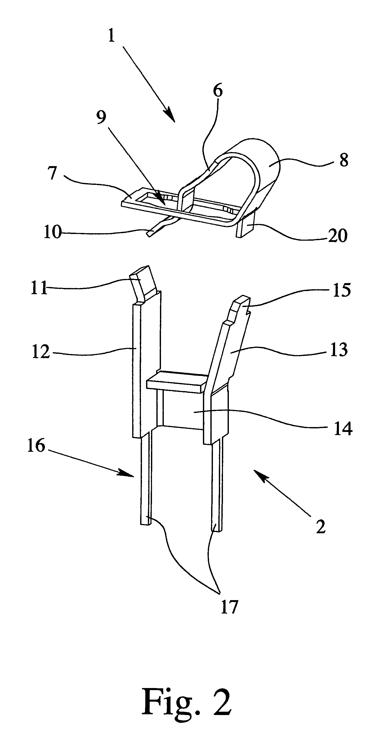
[0031]FIGS. 1 to 3 show a clamping spring 1 and a metal part 2 of a supply or connecting terminal which is shown altogether only in FIG. 1. The supply or connecting terminal includes an insulating housing 5 which has a conductor entry opening 3 for inlet of an electrical conductor 4 to be connected and in which the clamping spring 1 and the metal part 2 are located. The clamping spring 1 has a clamping leg 6, a contact leg 7 and a back 8 which connects the clamping leg 6 and the contact leg 7.

[0032]As FIG. 1 shows, the contact leg 7 of the clamping spring 1 is arranged essentially perpendicular to the insertion direction of the electrical conductor 4 to be connected in the insulating housing 5. In the contact leg 7 of the clamping spring 1, a recess 9 is formed for insertion of the electrical conductor 4 to be connected. If the electrical conductor 4 is inserted through the recess 9, the tip of the electrical conductor 4 is pressed by the end 10 of the clamping leg 6 against the met...


PUM


Abstract

An electrical supply or connecting terminal with a clamping spring and a metal part located in an insulating housing having a conductor inlet opening for an electrical conductor. The clamping spring has a clamping leg and a contact leg, and the clamping leg and the metal part form a spring force clamp connection for the electrical conductor. The contact leg of the clamping spring is arranged essentially perpendicular to the insertion direction of the electrical conductor and a recess is formed in the contact leg for insertion of the electrical conductor. The clamping leg and the contact leg of the clamping spring are bent toward one another with the end of the clamping leg extending through the recess. The metal part has at least one mounting section inserted through the recess of the clamping spring in a direction opposite the insertion direction of the electrical conductor.

Description

BACKGROUND OF THE INVENTION[0001]1. Field of Invention[0002]The invention relates to an electrical supply or connecting terminal with a clamping spring and with a metal part, the clamping spring and the metal part being located in an insulating housing which has an inlet conductor opening for entry of an electrical conductor which is to be connected, the clamping spring having a clamping leg and a contact leg, and the clamping leg and the metal part forming a spring force clamp connection for the electrical conductor to be connected.[0003]2. Description of Related Art[0004]Electrical terminal means or connecting means are used to establish an electrical terminal or electrical connection, specifically to produce an electrically conductive connection, a metallic connection, between a contact element and a mating contact element. Whether in the individual case there is a terminal means or a connecting means, is functionally relatively unimportant. It is often considered a terminal mean...

Claims


Application Information

Patent Timeline
Patent Type & Authority Patents(United States)
IPC IPC(8): H01R11/20H01R12/55
CPCH01R4/4827H01R4/48275
Inventor REIBKE, HEINZFEYE-HOHMANN, JUERGEN
Owner PHOENIX CONTACT GMBH & CO KG
Why Eureka
Try Eureka