Ring element for a rotor of an electric motor

a technology of ring element and electric motor, which is applied in the direction of windings, mechanical energy handling, windings insulation materials, etc., can solve the problems of insufficient fixation of the inner winding layer in the region of the end winding, the bending radius of the winding, and the inability to definitively fix the inner winding layer in the winding assembly, so as to achieve a longer service life and higher resistance to inter-winding shorts

Active Publication Date: 2014-05-22
ROBERT BOSCH GMBH
View PDF12 Cites 1 Cited by
  • Summary
  • Abstract
  • Description
  • Claims
  • Application Information

AI Technical Summary

Benefits of technology

[0012]In an independent aspect, the invention proposes a lamellar insulating element for an electric motor rotor for being wound with a rotor winding which comprises a ring element according to one of the preceding exemplary embodiments. The ring element may be formed in two parts with the lamellar insulating element and the parts connected to one another, for example adhesively bonded, made to engage or screwed together, or the lamellar insulating element may be formed in one piece with the ring element, for example formed in an injection-molding or foaming process, by means of a two-component technique, or an additional ring element may be fashioned from the lamellar insulating element by a forming process. Such a lamellar insulating element may be used in an existing design of a lamellar electric motor without changing the existing structure or the basic design, and consequently offers the advantages according to the invention.
[0013]In a further aspect, the invention proposes an electric motor, in particular a universal motor, i.e. a series-wound motor, which has a rotor with a rotor winding, on which at least one ring element according to one of the preceding exemplary embodiments is comprised. This makes the rotor winding mechanically and thermally more robust, and so a longer service life and higher resistance to inter-winding shorts can be achieved, in particular in the region of the end windings.

Problems solved by technology

For instance, in the compact installation space, the inner layers of the rotor windings have a very small bending radius, the wire coils being exposed to a high thermal loads and having to withstand centrifugal forces.
However, the innermost winding layer cannot be definitively fixed in the winding assembly, lying as it were in free space in the region of the end windings at one axial end region of the winding section of the electric motor rotor and resin fixing being unable to take hold.
This gives rise to the problem that the inner winding layer is not sufficiently fixed in the region of the end windings and is insufficiently protected from both thermal and mechanical loads, in particular from high vibrations and centrifugal forces.

Method used


Image

  • Ring element for a rotor of an electric motor
  • Ring element for a rotor of an electric motor
  • Ring element for a rotor of an electric motor

Examples


Embodiment Construction

[0024]In the figures, components that are the same or similar are denoted by the same reference numerals.

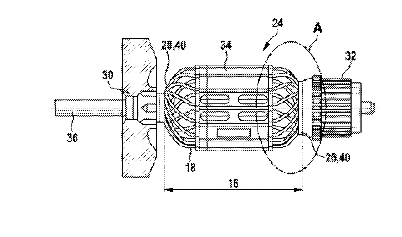
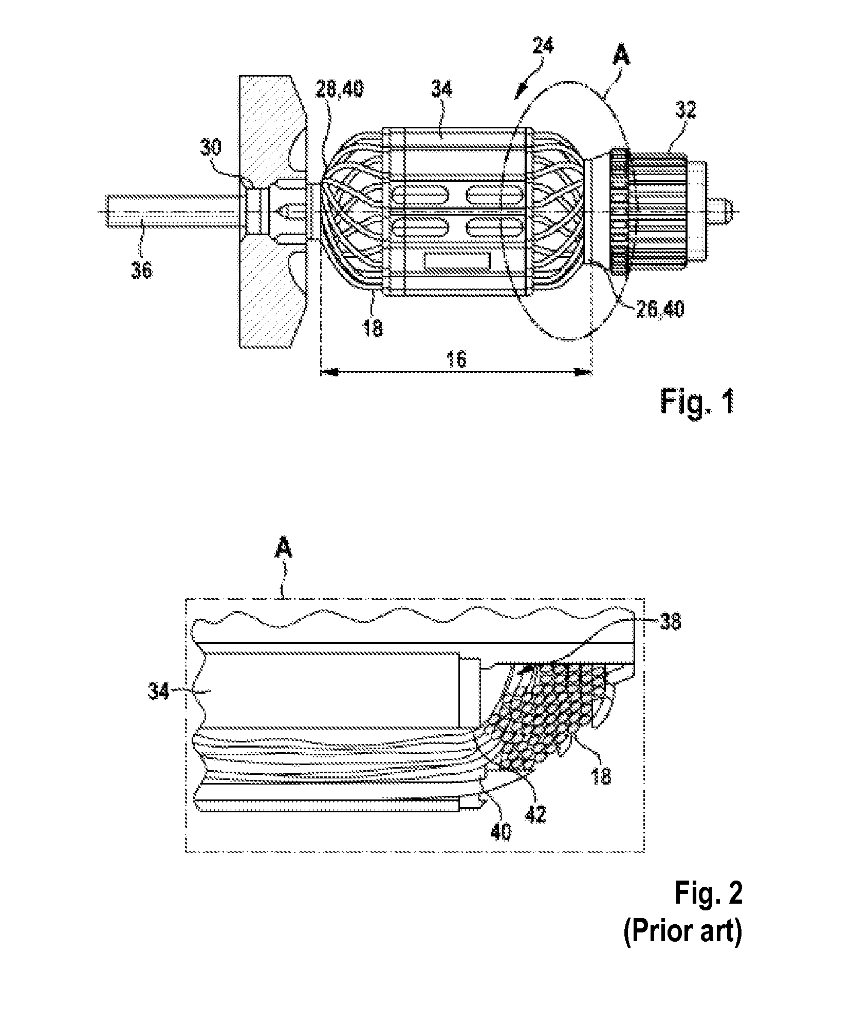
[0025]For an explanation of the invention, FIG. 1 shows in a side view a rotor 24 of a universal motor, in which a rotor winding 18 is wound along a laminated rotor core 34. The rotor 24 has a rotor spindle 36, along which all the rotating parts of the rotor are arranged for rotation therewith. The laminated rotor core 34 bears the winding 18, which are formed at both its axial end regions 26, 28 into end windings 40. In this case, a first end region 28 is assigned to the bearing 30 of the rotor 24, and a second end region 26 is assigned to the commutator 32 of the rotor 24. At the commutator 32, current is transferred via carbon brushes (not represented) to the rotor winding 18, a constantly rotating magnetic field being generated by rotation of the rotor as a result of current being applied in an alternating manner to the rotor winding 18 in the rotor 24. For the directed guida...


PUM


Abstract

A ring element includes a convex, in particular rounded, surface element for arrangement on at least one axial end region of a winding section of an electric motor rotor. The surface element provides a minimum radius curvature for supporting an inner layer of a rotor winding on the winding head. An insulating lamination element for an electric motor rotor onto which a rotor winding is intended to be wound includes the ring element. An electric motor, in particular a universal motor, includes a rotor with a rotor winding having the ring element. An electric machine tool, in particular a handheld electric machine tool such as an angle grinder, a drill, a saw or the like, includes the electric motor.

Description

PRIOR ART[0001]The invention is based on a ring element to be arranged at at least one axial end region of a winding section of an electric motor rotor. Furthermore, the invention relates to a lamellar insulating element which comprises a ring element according to the invention. Finally, the invention relates to an electric motor on the rotor of which such a ring element is arranged, and to an electrical power tool that comprises an electric motor according to the invention.[0002]Universal motors, i.e. series-wound motors in which the rotors bear a rotor winding that is supplied with current via a commutator, are generally used in electric motors for electric power tools, in particular an angle grinder, a drill, a saw, jigsaws or the like. In the region of the end windings at the axial end regions of a winding section, the inner layers of the winding in particular have a small radius of curvature and are exposed to high mechanical and thermal loads. For instance, in the compact inst...

Claims


Application Information

Patent Timeline
Patent Type & Authority Applications(United States)
IPC IPC(8): H02K3/50H02K7/14H02K3/30
CPCH02K3/51H02K3/38H02K7/145H02K3/30H02K3/50
Inventor EFFLER, JOSEFWAGNER, CHRISTOPHSCHADOW, JOACHIMHEIN, JUERGENGOEHNER, JOERG
Owner ROBERT BOSCH GMBH
Why Eureka
Try Eureka