

Manipulator for the assembly of rotor blades of a wind power installation
a technology for manipulating and wind power installations, which is applied in the direction of wind energy generation, motors, cranes, etc., can solve the problems of increasing assembly time, increasing assembly costs, and increasing assembly costs, so as to reduce assembly time and assembly costs
- Summary
- Abstract
- Description
- Claims
- Application Information
AI Technical Summary
Benefits of technology
Problems solved by technology
Method used
Image

Examples
second embodiment
[0038]a manipulator in accordance with the invention is shown in FIG. 4 which is arranged at a boom 100 of a telescopic crane. The manipulator is in this respect mounted on the roller head 90 of the boom so that the hoist rope can remain reeved in the roller head. A fully adequate crane operation is hereby also possible with a mounted manipulator. The hoist rope 80, which is reeved in the roller head 90, carries a crane hook 85 in this respect. The mounting of the manipulator in this respect takes place at the roller head via bolted connections 98 to which a lattice tip can be mounted in a conventional manner. An adapter 101 is provided for this purpose which is connected to the roller head 90 at the bolted connections 98. The manipulator is mounted at the adapter 101 via bolted connections 99. The manipulator in FIG. 4 in this respect has two swiveling crowns 60 and 70 whose axes of rotation are perpendicular to one another. The axis of rotation of the first swiveling crown is in t...
third embodiment
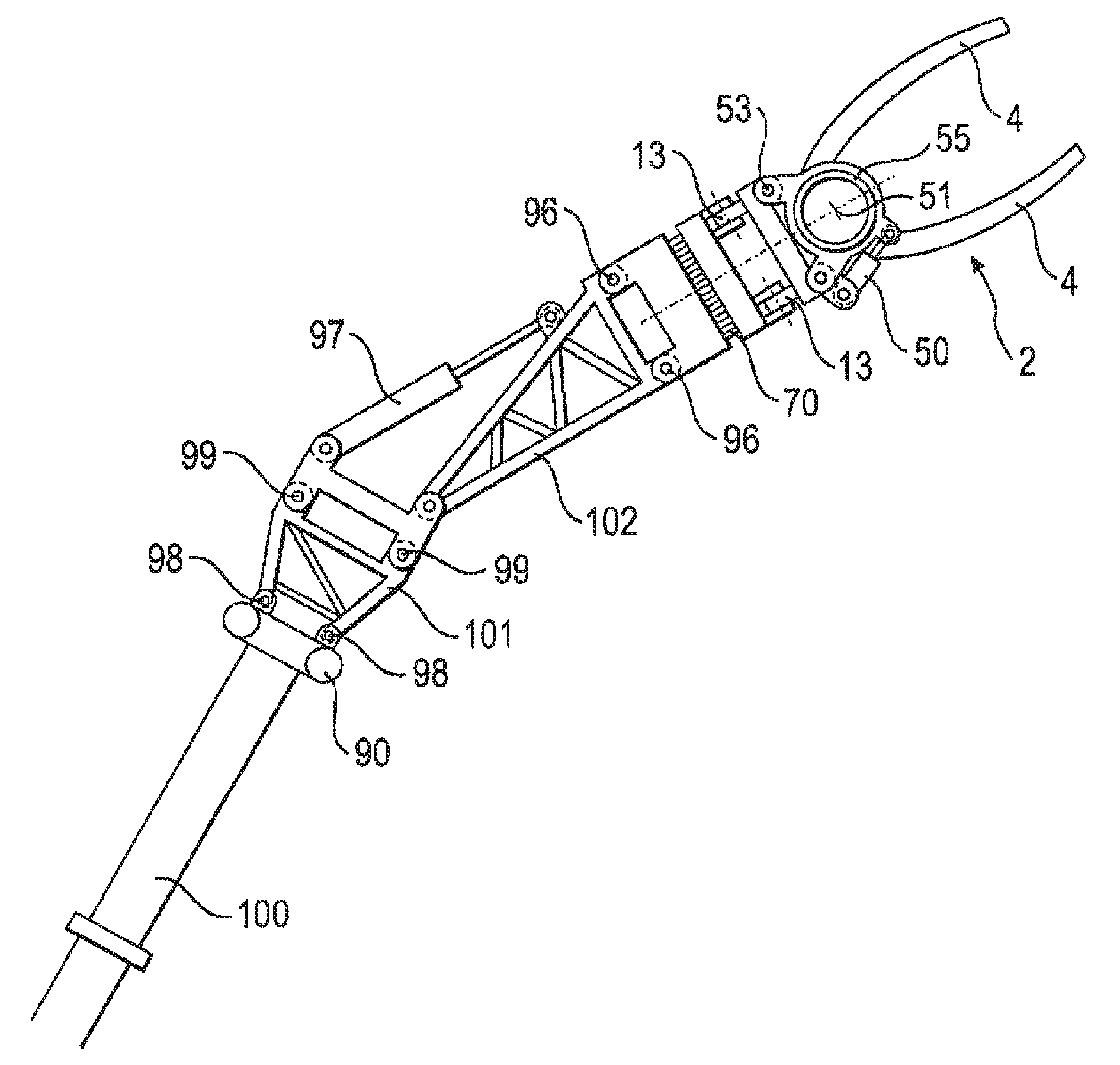
[0039]a manipulator in accordance with the invention is shown in FIGS. 5c and 5c. The receiving unit having the receiving tools 4 which are arranged at the longitudinal element 55 is in this respect pivotable about the axis of rotation 51 of the longitudinal element, for which purpose the hydraulic cylinder 50 is provided. This makes it possible to pivot the rotor blade, which is received along its longitudinal axis at two points by the receiving tools, about the axis of rotation 51 extending parallel to the longitudinal axis of the rotor blade. The positioning apparatus of the manipulator furthermore has a swiveling crown 70 as well as a tilt joint 13 which is driven via hydraulic cylinders. The receiving tool is mounted at bolted connection points 53 at the tilt joint 13, while the manipulator is bolted to the crane via bolted connection points 96.
[0040]In this connection, the manipulator shown in FIG. 5c and d is mounted at a luffing fly jib 102. The luffing fly jib is in this re...
fourth embodiment
[0041]the manipulator in accordance with the invention is shown in FIGS. 7a and 7b which has two swiveling crowns 70 and 71 as well as one tilt joint 13. The two swiveling crowns 70 and 71 in turn have axes of rotation which are perpendicular to one another. In this respect, the axis of rotation of the first swiveling crown 71, arranged at the crane side, extends in a plane perpendicular to the longitudinal axis of the boom 100, while the axis of rotation of the second swiveling crown 70 extends in a plane which is perpendicular to the axis of rotation of the first swiveling crown. The swiveling crowns are in this respect movable via respective rotary drives. The tilt joint 13 is tiltable via hydraulic cylinders 12. The movability of the tilt joint 13 amounts in this respect to around 45° in each case in both directions of movement. The second swiveling crown allows a rotation about 360°; the second swiveling crown 71, in contrast, only allows a movement about around 120° in both di...
PUM
 Abstract
Description
Claims
Application Information