Quick-connect/quick-disconnect conduit connectors

a technology of quick-connect and connector, which is applied in the direction of sleeve/socket joint, laundry drier, textiles and paper, etc., can solve the problems of difficult use of clamp types, inability to align screwdrivers with machine screws, and difficulty in sliding conduit onto the pipe to allow secure clamping, etc., to achieve easy and quick detachable, fast and secure means, and simple economic

Inactive Publication Date: 2005-08-25
STRAVITZ DAVID M
View PDF32 Cites 17 Cited by
  • Summary
  • Abstract
  • Description
  • Claims
  • Application Information

AI Technical Summary

Benefits of technology

[0013] Accordingly, it is an object of the present invention to provide a quick connect device that constitutes a simple economical, fast and secure means for coupling or attaching an exhaust conduit to the dryer vent or exhaust pipe of a clothes dryer or the like, and which also is easily and quickly detachable from such a conduit.
[0014] It is another object of the present invention to provide a connector for connecting conduits together which does not require twisting of any of the conduits and thereby avoids the potential for kinking of the conduits and / or damaging the free ends of the conduits during the connecting procedure.
[0017] Locking flanges are preferably provided on inner surfaces of one or both of the semi-cylindrical members to engage with the tubular components. The locking flanges thus enhance the attachment of the connector to the tubular components. To limit penetration of the tubular components into the connector, a divider flange may also be formed on the inner surfaces of the semi-cylindrical members and is provided with a larger height than the locking flanges.
[0021] Still another type of connector for connecting a pair of tubular components together includes an elongate strap of flexible material having opposite free edges and a quick connect / quick disconnect locking structure for locking the free edges together at different distances therebetween to thereby enable the strap to encircle tubular components having different sizes. The locking structure may include a pivotable tension lever arranged at one free edge and a projection arranged at the other free edge. The projection has several notches spaced at different distances from the free edge. As such, the tension lever can engage with any of the notches to thereby enable variation in the distance between the free edges of the strap.

Problems solved by technology

These types of clamps are difficult to use because dryers are often installed with minimal working space around the exhaust pipe.
The exhaust conduit fits over the pipe and, because there is little working room, it is hard to slide the conduit onto the pipe to allow secure clamping.
However, a screwdriver cannot be aligned with the machine screw, because the clamp must be inside the plane of the dryer back in order to clamp the conduit on the pipe.
This installation procedure is awkward and frequently results in an insecure clamping which can lead to the conduit slipping off of the exhaust pipe later when the dryer is vibrating during an operating cycle.
This is also a difficult feat which produces the same disadvantageous results as the first type of clamp described.
Dawson does not disclose a connector for connecting a pair of exhaust conduits together.

Method used


Image

  • Quick-connect/quick-disconnect conduit connectors
  • Quick-connect/quick-disconnect conduit connectors
  • Quick-connect/quick-disconnect conduit connectors

Examples


first embodiment

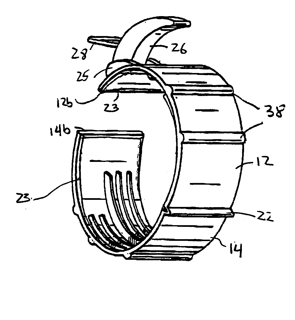
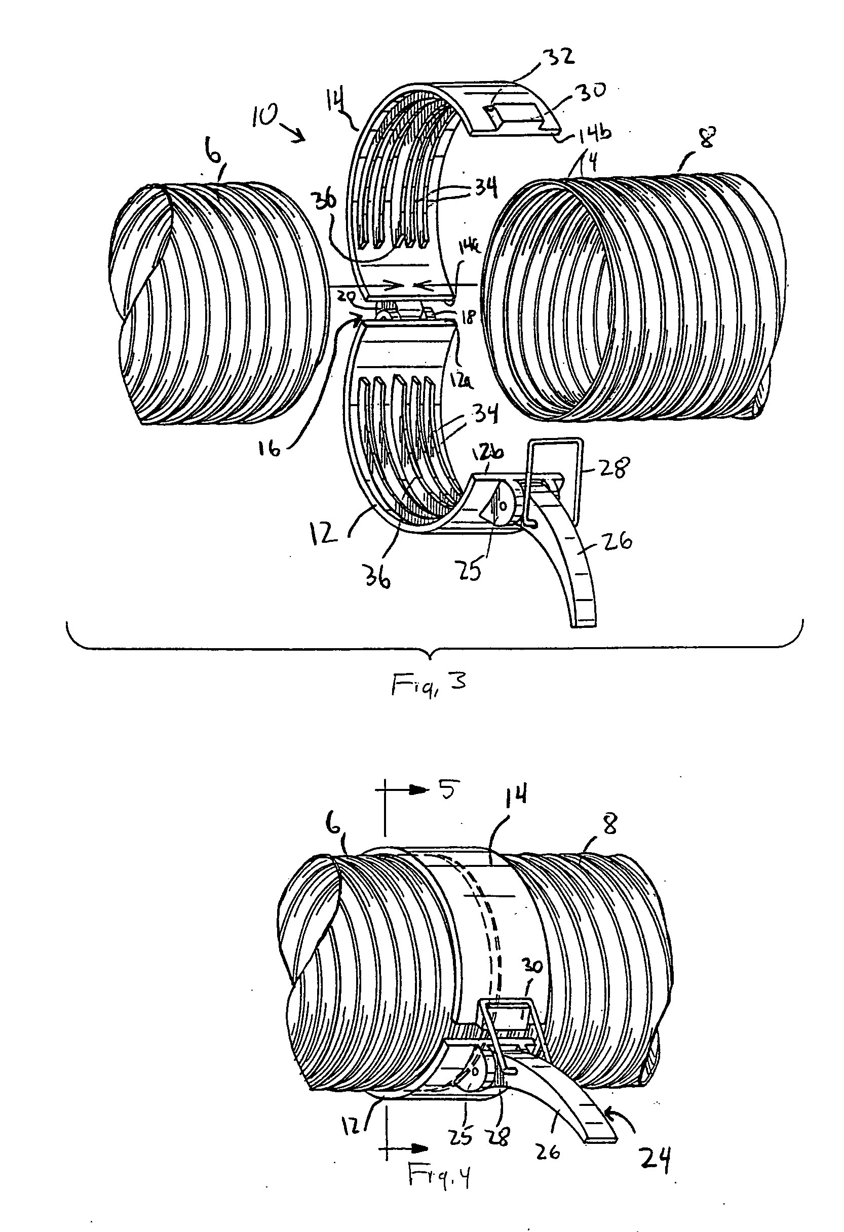
[0049] Referring to the accompanying drawings wherein like reference numerals refer to the same or similar elements, a connector for connecting a pair of conduits in accordance with the invention is designated generally as 10. The connector 10 includes a pair of generally semi-cylindrical members 12, 14 rotatably connected together at a first, coupled edge 12a, 14a and separable from one another at a second, free edge 12b, 14b. In this manner, the semi-cylindrical members 12, 14 have an open position in which the second edges 12b, 14b are separated from one another (as shown in FIG. 3) and a closed position in which the second edges 12b, 14b are adjacent one another (as shown in FIG. 5).

[0050] In the embodiment shown in FIG. 3, the semi-cylindrical members 12, 14 are connected together by a hinge 16 (i.e., connected at the first edges 12a, 14a). Hinge 16 may have any known structure in the art, for example, a first part 18 defining a pivot axis arranged on or integrally formed in co...

second embodiment

[0086] Referring now to FIGS. 9, 9A and 10, a connector for connecting two conduits 6, 8 together, in particular conduits having different diameters, is designated generally as 62. The connector 62 includes a pair of generally semi-cylindrical members 64, 66 rotatably connected together at a first, coupled edge 64a, 66a and separable from one another at a second, free edge 64b, 66b. The semi-cylindrical members 64, 66 thus have an open position in which the second edges 64b, 66b are separated from one another (as shown in FIG. 9) and a closed position in which the second edges 64b, 66b are adjacent one another (as shown in FIG. 10).

[0087] The semi-cylindrical member 64 includes a first engagement portion 68 adapted to engage with the smaller conduit 6 and a second engagement portion 70 adapted to engage with the larger conduit 8. An arcuate lip 72 is formed between the engagement portions 68, 70 and is perpendicular to an axis passing through the connector 62. Similarly, the semi-cy...


PUM


Abstract

Connector for connecting a pair of tubular components together, such as a pair of exhaust conduits of a dryer or an exhaust conduit of a dryer to a dryer vent or wall-mounted vent sleeve, including a pair of generally semi-cylindrical members each having a first, coupled edge and a second, free edge and rotatably connected together at the coupled edge, e.g., by a hinge, and separable from one another at the free edge. A quick connect / wuick disconnect locking structure is arranged in connection with the semi-cylindrical members for locking them to one another with the free edges opposite one another.

Description

FIELD OF THE INVENTION [0001] The present invention relates generally to quick connect / quick disconnect connectors for connecting a pair of tubular components together, and more particularly, to such connectors for connecting together exhaust conduits of a clothes dryer or any other type(s) of conduits. [0002] The present invention also relates to connectors for connecting flexible tubular components (such as conduits) to rigid tubular components, and more particularly, to such connectors for connecting an exhaust conduit to a dryer vent of a clothes dryer and / or to a vent pipe or other vent member. BACKGROUND OF THE INVENTION [0003] In the fluid conveyance art, there is a need for connectors which connect a pair of flexible or non-flexible fluid-conveying conduits together and which connect a flexible conduit to a rigid pipe or pipe-shaped member. For example, to vent exhaust air from a clothes dryer, the clothes dryer is usually installed with a flexible conduit extending between ...

Claims


Application Information

Patent Timeline
Patent Type & Authority Applications(United States)
IPC IPC(8): F16L21/06F16L25/00
CPCD06F58/20F16L21/06Y10S285/903F16L25/0045F16L25/14F16L25/0036
Inventor STRAVITZ, DAVID M.
Owner STRAVITZ DAVID M
Why Eureka
Try Eureka