
Rotary type dusting device

a dusting device and rotary technology, applied in the direction of vacuum cleaners, carpet cleaners, applications, etc., can solve the problems of time-consuming and labor-intensive both ways, difficult to wash strips, and ineffective bristles, etc., to achieve easy and quick attachment and reduce assembly costs

Inactive Publication Date: 2016-11-17
YANG YA CHING +2
View PDF11 Cites 18 Cited by
  • Summary
  • Abstract
  • Description
  • Claims
  • Application Information

AI Technical Summary

Benefits of technology

The present invention provides a rotary type dusting device that can be detachably assembled to an automatic cleaning machine and provides simultaneous sweeping and dust-absorbing effects, resulting in double the efficiency of dusting work with half the effort. The device is equipped with easily and quickly detachable dusting components, which allows for low-cost and high-efficiency dusting work. The rotary disc includes a plurality of restraining portions to prevent deformation of the bristle bundles and provide better quality cleaning. The device firstly utilizes the rotation of the bristle bundles for sweeping and then utilizes the rotation of the dusting element for cleaning and removing remaining dust, providing a dual-effect dusting work. The device is convenient to assemble or detach from the rotary disc, lowering the cost of assembly and overcoming drawbacks of conventional vacuum cleaners.

Problems solved by technology

However, both ways as mentioned above are time-consuming and laborious.
However, the bristles do not work effectively, especially for dirt or splotches on the floor.
Moreover, the rotary element itself must not come into contact with water while the strips are washed, and this makes it difficult to wash the strips.
In addition, the strips are likely to fall off when rotated and, if happening, will hinder the floor cleaning process.
Also, the strips alone cannot be replaced after they have been used for a while; the rotary element must be replaced together with the strips, which incurs a considerable cost.
However, the cleaning machine is not moving in a fixed direction, and the wheels are likely to leave dirt from itself on the floor when the cleaning machine is moving.
Therefore, the rotary element configured in front of the wheels cannot efficiently clean the dirt left by the wheels.

Method used


Image

  • Rotary type dusting device
  • Rotary type dusting device
  • Rotary type dusting device

Examples


Embodiment Construction

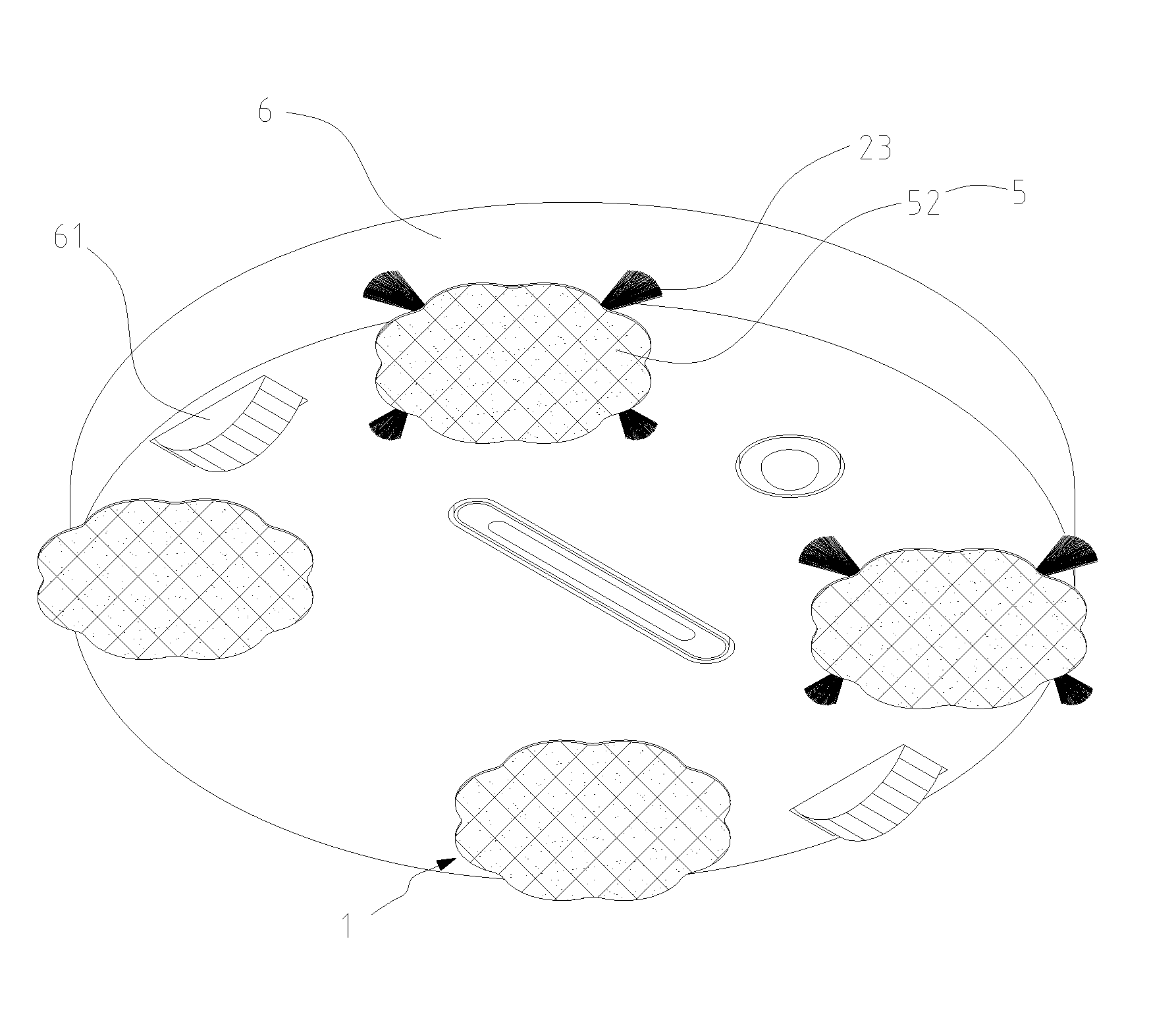
[0020]Referring to FIGS. 1 to 6 showing a preferred embodiment of a rotary type dusting device 1 of the present invention, the rotary type dusting device 1 is detachably assembled to an automatic cleaning machine 6. The automatic cleaning machine 6 functions as a vacuum cleaner and is equipped with two wheels 61 at a bottom thereof for allowing the automatic cleaning machine 6 to move automatically without manual control.

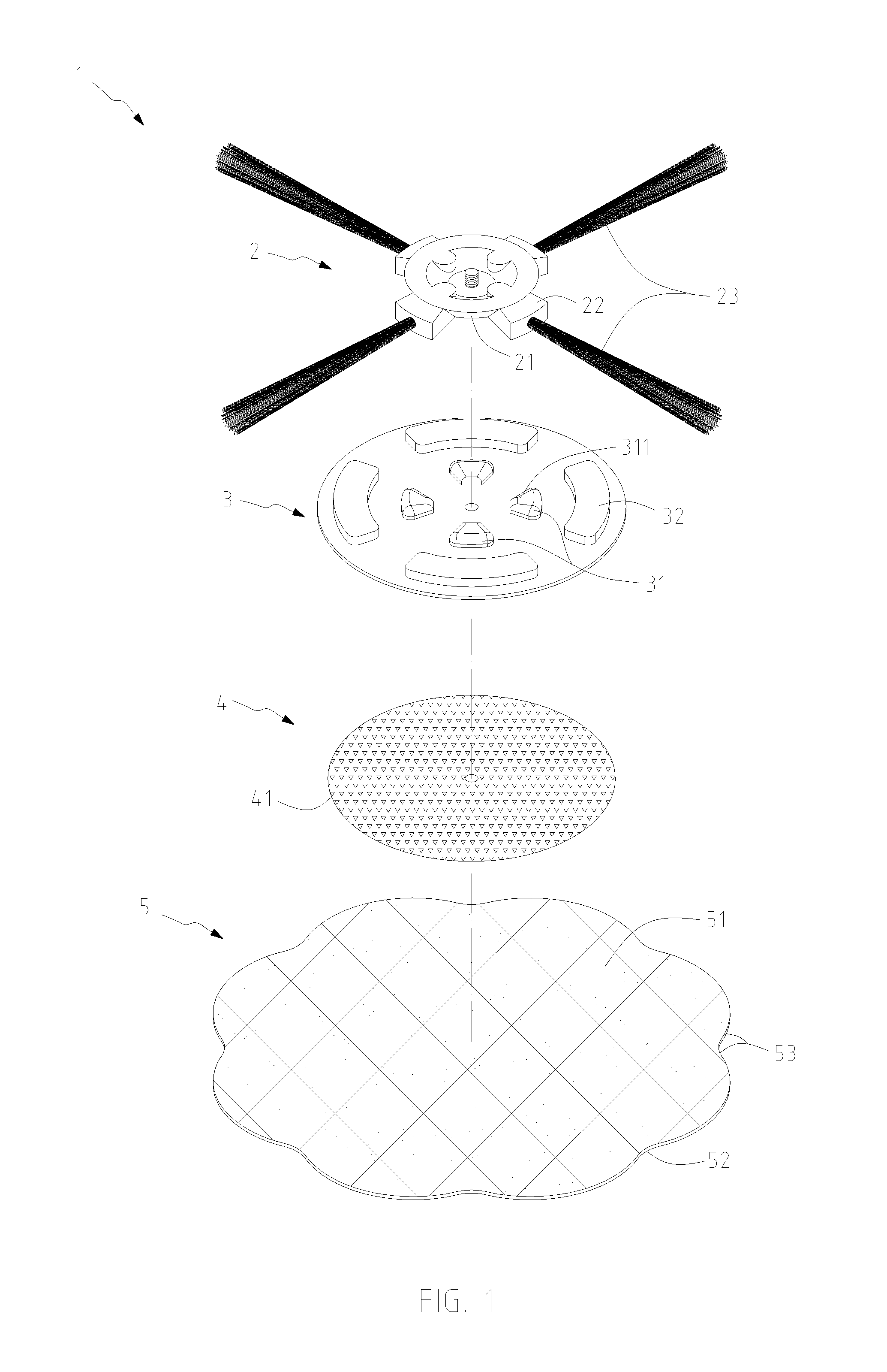
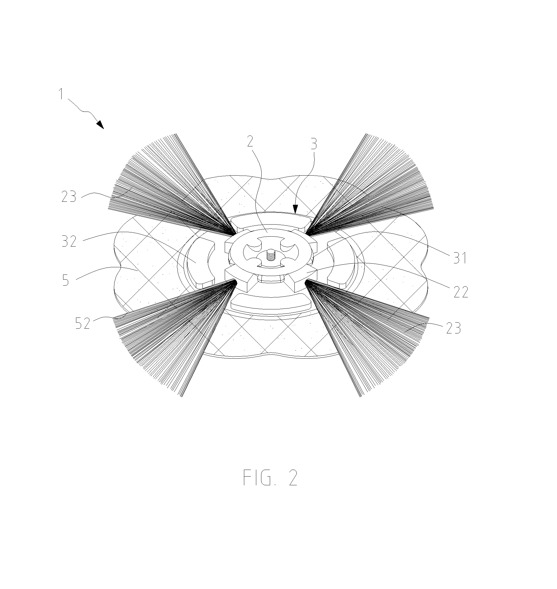
[0021]The rotary type dusting device 1 comprises a connecting base 2, a rotary disc 3, an affixing element 4, and a dusting element 5. The connecting base 2 is pivotably connected to the bottom of the automatic cleaning machine 6 through a drive shaft (not shown) connected to a built-in motor (not shown) so as to be driven by the drive shaft to rotate. In this embodiment, the connecting base 2 has a round shape and comprises a plurality of interference portions 21 and mounting portions 22 arranged around the connecting base 2. The interference portions 21 are arrang...


PUM


Abstract

A rotary type dusting device, detachably assembled to an automatic cleaning machine, the rotary type dusting device includes a connecting base, a rotary disc, an affixing element, and a dusting element. The connecting base is driven by the cleaning machine to rotate and includes a plurality of interference portions and mounting portions for mounting bristles. The rotary disc is detachably connected to a bottom of the connecting base and is rotatable in conjunction with the connecting base. The rotary disc includes a plurality of positioning portions spaced apart from each other for correspondingly engaging the interference portions. The affixing element is fixed onto a bottom of the rotary disc for attaching the dusting element, so that the dusting element is rotatable in conjunction with the rotary disc and the bristles to carry out dusting and sweeping work.

Description

BACKGROUND OF THE INVENTION[0001]1. Field of the Invention[0002]The present invention relates to a dusting device and, more particularly, to a rotary type dusting device which is rotatable to perform sweeping as well as dusting.[0003]2. Related Art[0004]The prerequisite step of floor dusting is to sweep the floor. The ways to sweep as known is performed with a sweep or a rag by humans. However, both ways as mentioned above are time-consuming and laborious. Although a vacuum cleaner can be used to suck up dust and dirt, it is still needed to be controlled manually for its moving.[0005]To increase the efficiency of the prerequisite cleaning step, automatic cleaning machines which collect dust by suction were developed. These machines are configured to suck in dust from the bottom while moving, or are equipped with a bristled tool for brushing the floor being vacuum-cleaned. A traditional automatic cleaning machine typically operates on a built-in motor, which drives a rotary element i...

Claims


Application Information

Patent Timeline
IPC IPC(8): A47L11/24A47L9/04
CPCA47L11/24A47L9/0488A47L9/0472A47L11/4038A47L11/4069A47L2201/00
Inventor YANG, YA-CHINGPAN, YI-JUNLIN, PAI-YUNG
Owner YANG YA CHING
Learn More