Eureka AIR delivers breakthrough ideas for toughest innovation challenges, trusted by R&D personnel around the world.

Packet communication system, packet communication method, base station, mobile station, controller and packet communication program

a packet communication and packet communication technology, applied in multiplex communication, wireless commuication services, power management, etc., can solve problems such as packet reception failure in many cases, large fluctuation of interference level (interference power) in mobile stations belonging to another cell, and deterioration of communication quality, so as to improve system capacity and quality of service. , the effect of increasing the interference level

Active Publication Date: 2005-08-25
NTT DOCOMO INC
View PDF10 Cites 21 Cited by
  • Summary
  • Abstract
  • Description
  • Claims
  • Application Information

AI Technical Summary

Benefits of technology

[0009] The present invention was made in consideration of the above circumstances, It is an object of the present invention to provide a packet communications system, a packet communications method, a base station, a mobile station, a control device and a packet communications program, which are capable of improving satisfaction rate with a system capacity and a quality of service (QoS) by dynamically limiting transmission power of packets in a transmitting station and keeping an increase of an interference level in a receiving station belonging to another cell within a TPC margin.
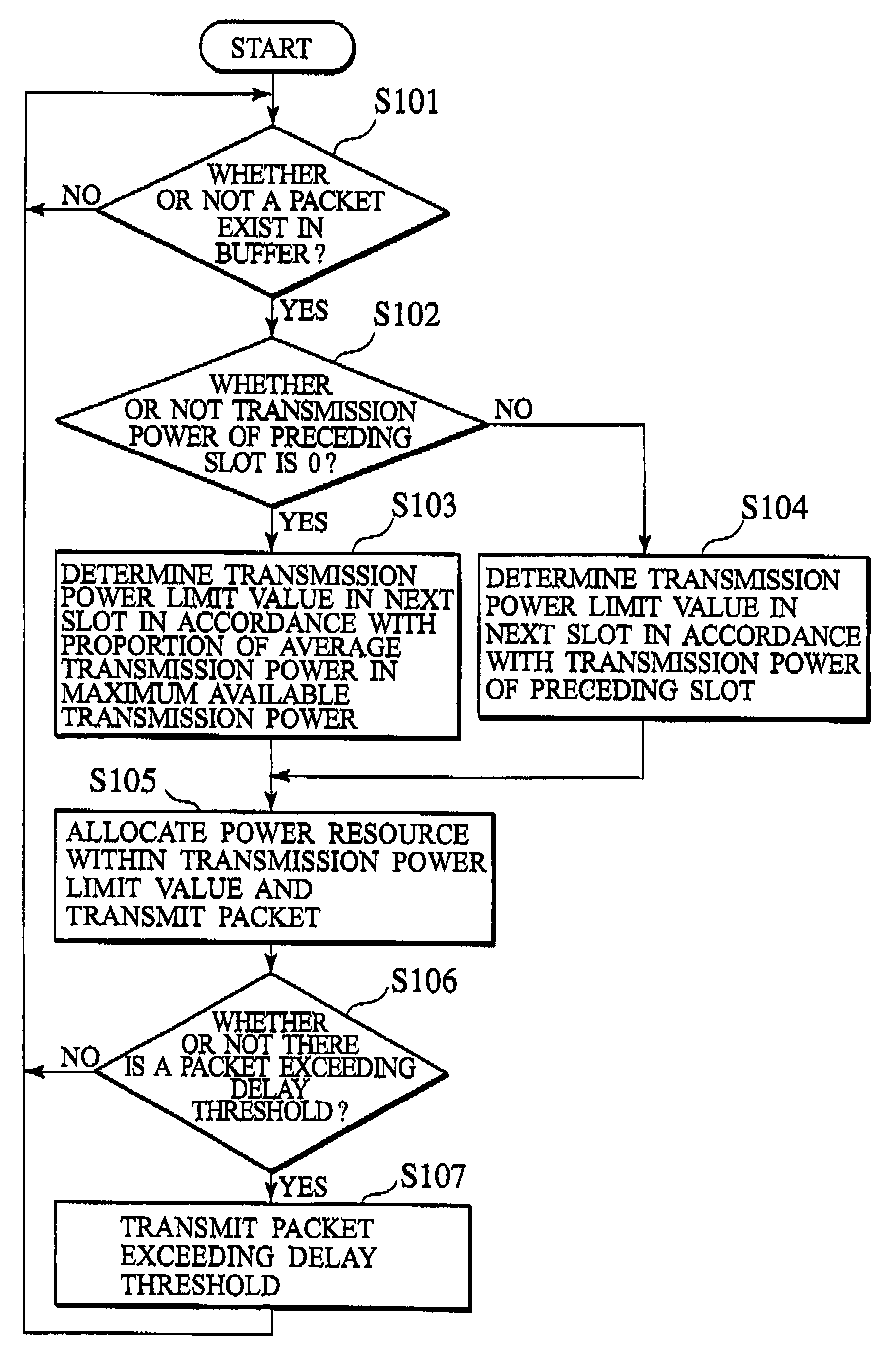
[0030] A sixth aspect of the present invention is summarized as a packet communications program which performs packet communications through a radio link established between a transmitting station and a receiving station. The program allows a computer to execute processing of setting transmission power of packets in a next step period by use of transmission power of packets in a preceding step period and an interference level of the receiving station.

Problems solved by technology

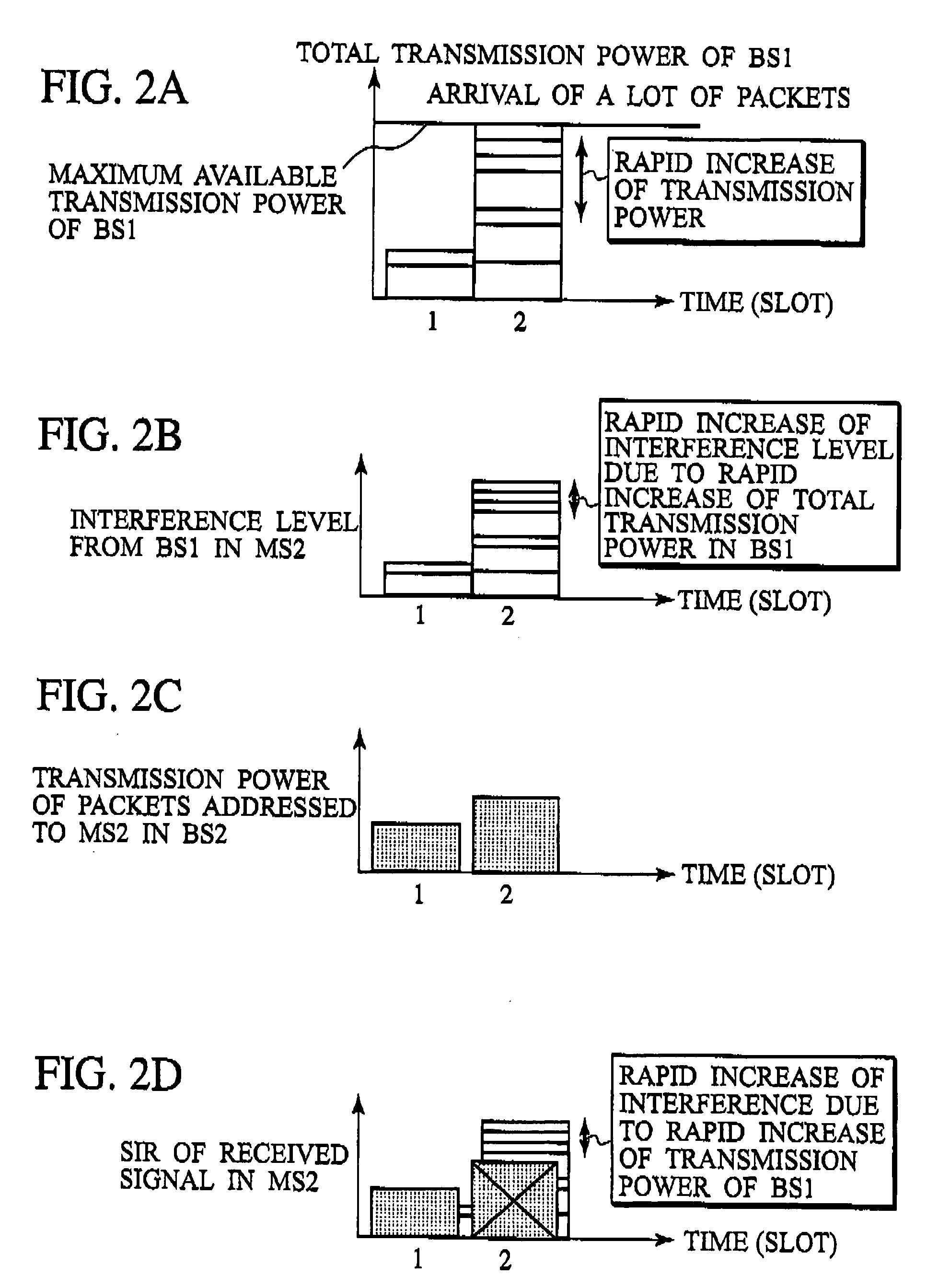
Thus, fluctuation of an interference level (interference power) in a mobile station belonging to another cell becomes large.
As described above, the conventional packet communications system described above has a drawback in that, regardless of the TPC margin, the rapid increase of the interference level in the receiving station due to burstiness of packets causes the packet reception failure in many cases.
Moreover, there is a drawback in that such packet reception failure deteriorates a communications quality and decreases a system capacity.

Method used


Image

  • Packet communication system, packet communication method, base station, mobile station, controller and packet communication program
  • Packet communication system, packet communication method, base station, mobile station, controller and packet communication program
  • Packet communication system, packet communication method, base station, mobile station, controller and packet communication program

Examples


first embodiment

Overview of Packet Communications System and Packet Communications Method According to this Embodiment

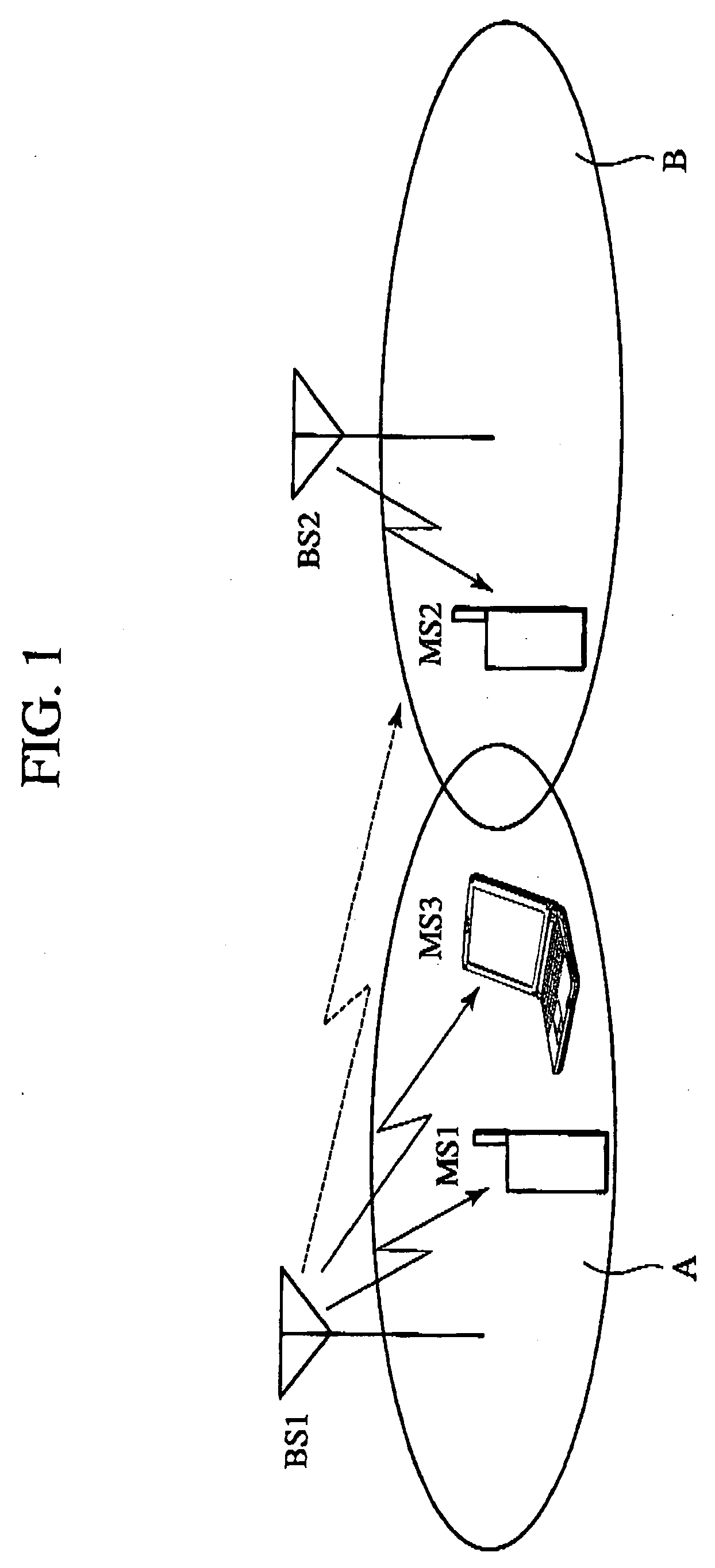
[0067] Detailed description will be given below of a packet communications system and a packet communications method according to a first embodiment of the present invention. FIG. 3 is an explanatory view showing an overview of the packet communications system according to this embodiment.

[0068] Note that, in the packet communications system according to this embodiment, a base station (transmitting station) BS2 controls transmission power of packets addressed to a mobile station (receiving station) MS2 in a downlink (a direction toward the mobile station MS2 from the base station BS2).

[0069] As shown in FIG. 3, in the packet communications system according to this embodiment, a base station BS1 controlling a cell “A” and the base station BS2 controlling a cell “B” adjacent to the cell “A” are disposed. Mobile stations MS1 and MS3 are located in the cell “A” and the mobile statio...

second embodiment

Overview of Packet Communications System and Packet Communications Method According to this Embodiment

[0131] Next, detailed description will be given of a packet communications system and a packet communications method according to a second embodiment of the present invention. FIG. 9 is an explanatory view showing an overview of the packet communications system according to this embodiment.

[0132] Note that, in the packet communications system according to this embodiment, a mobile station (transmitting station) MS3 is configured to control transmission power of a packet addressed to a base station (receiving station) BS1 in an uplink (a direction toward the base station BS1 from the mobile station MS3).

[0133] As shown in FIG. 9, in the packet communications system according to this embodiment, the base station BS1 controlling a cell “A” and a base station BS2 controlling a cell “B” adjacent to the cell “A” are disposed. Mobile stations MS1 and MS3 are located in the cell “A”, and...

third embodiment

[0168] Next, with reference to FIGS. 17 to 19, a packet communications system and a packet communications method according to a third embodiment of the present invention will be described. FIG. 17 is a functional block diagram of a base station BS1 according to this embodiment and FIG. 18 is a functional block diagram of a mobile station MS3 according to this embodiment.

[0169] Hereinafter, description will be given of differences between the packet communications system and the packet communications method according to this embodiment and the packet communications systems and the packet communications methods according to the first and second embodiments described above.

[0170] As shown in FIG. 17, the base station BS according to this embodiment includes a reception power storage circuit 119 in addition to the functions of the base station BS according to the first embodiment shown in FIG. 7.

[0171] The reception power storage circuit 119 is a circuit configured to store a sum of ...


PUM


Abstract

The present invention improves a system capacity and satisfaction rate with a quality of service in packet communications performed through a radio link established between a transmitting station and a receiving station by dynamically limiting transmission power of packets in the transmitting station and keeping an increase of an interference level in the receiving station, which belongs to another cell, within a TPC margin. The present invention includes a resource allocator 115 configured to set transmission power of packets in a next step period, by use of transmission power of packets in a preceding step period (slot) and an interference level of the receiving station.

Description

TECHNICAL FIELD [0001] The present invention relates to a packet communications system, a packet communications method, a base station, a mobile station, a control device and a packet communications program, all of which are for performing packet communications through a radio link established between a transmitting station and a receiving station. BACKGROUND ART [0002] In a conventional packet communications system, upon receipt of a packet addressed to a mobile station, a base station allocates radio resources (power resources and the like) up to maximum available transmission power of the base station, and transmits the packet to the mobile station. For example, in a CDMA system, upon receipt of a packet addressed to a mobile station, a base station allocates code resources up to maximum available transmission power of the base station, and transmits the packet to the mobile station. [0003] In the conventional packet communications system as described above, when packets arrive a...

Claims


Application Information

Patent Timeline
IPC IPC(8): H04B1/707H04B7/005H04J13/00H04W16/14H04W28/04H04W52/04H04W52/06H04W52/22H04W52/24H04W52/26H04W52/28H04W52/30H04W52/36
CPCH04W16/14H04W28/04H04W52/22H04W52/221H04W52/223H04W52/225H04W52/367H04W52/228H04W52/24H04W52/243H04W52/265H04W52/286H04W52/226H04W24/00
Inventor CHEN, LANKITAZAWA, DAISUKEKAYAMA, HIDETOSHIUMEDA, NARUMI
Owner NTT DOCOMO INC
Why Eureka
Eureka Blog
Learn More