Child booster seat

a booster seat and child technology, applied in the field of child restraint systems, can solve the problems of inability to adjust to allow a better fit, increase the risk of injury, and increase the amount of packaging and space required, so as to facilitate storage, reduce the risk of injury, and maintain the child comfortably and effectively.

Inactive Publication Date: 2005-09-01
COSCO MANAGEMENT INC
View PDF35 Cites 20 Cited by
  • Summary
  • Abstract
  • Description
  • Claims
  • Application Information

AI Technical Summary

Benefits of technology

[0009] It is another aim of the present invention to provide a child booster seat that can be easily stored using a minimum of space.
[0010] It is a further aim of the present invention to provide a child booster seat that can comfortably and effectively maintain a child in a position in which the child can be safely restrained by a car seat belt.
[0011] It is yet another aim of the present invention to provide a child booster seat with a cup holder that is stably installed at a first position thereof yet easily removed and installed at a second position thereof.

Problems solved by technology

Such booster seats present a number of disadvantages, one of which is the fact that they cannot be adjusted to allow a better fit either with the child sitting therein or with the car seat they are installed on.
However, the guiding device approximately doubles the height of the back rest, which implies larger packaging and more space required to store the booster seat when it is not in use.
However, the restraining means to maintain the height of the headrest are easily accessible to the child, with a possible risk of injury thereto.
Belt guides are located at the extremities of the side guards of the headrest, advancing the belt away from the child with a possibility of placing it too high when the headrest is elevated, thereby diminishing the seat belt efficiency.
In addition, the shape of the seat is not likely to be able to properly maintain a sleeping child in a position where the seat belt can be effective.
While the cup holder is easily removable, this configuration does not offer the stability brought by a rigidly fixed cup holder, thereby increasing the risk of spills.

Method used


Image

  • Child booster seat
  • Child booster seat
  • Child booster seat

Examples


Embodiment Construction

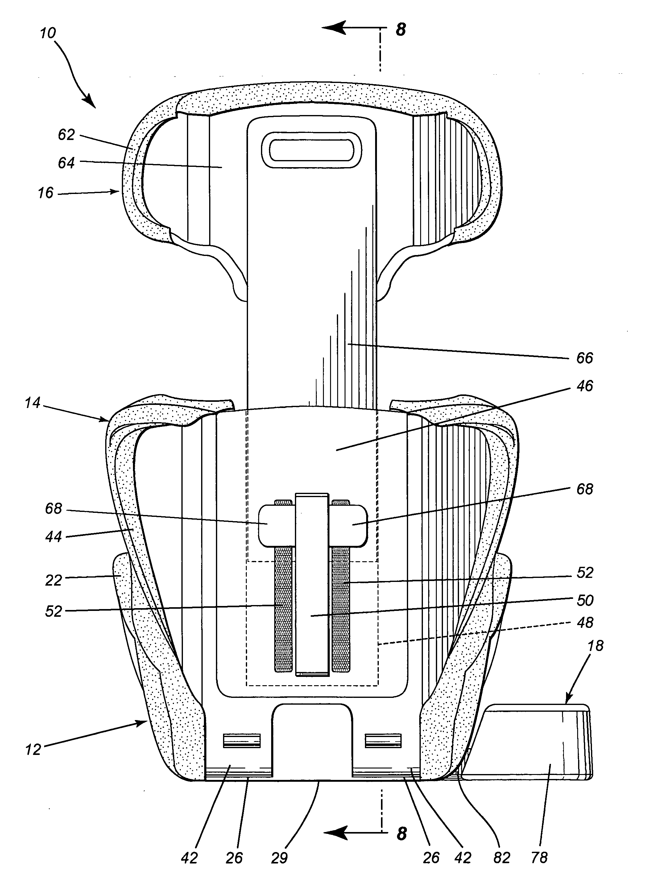
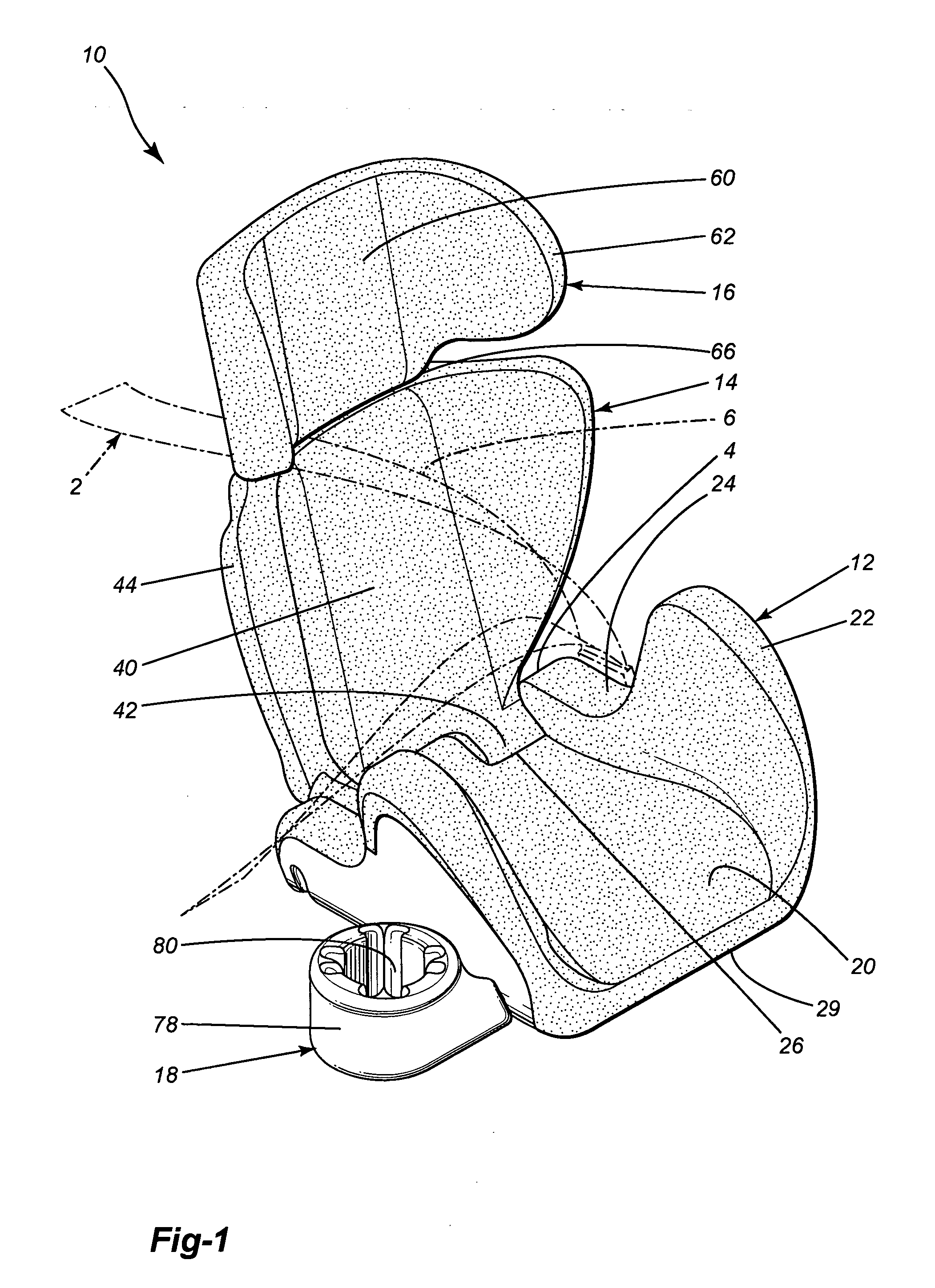
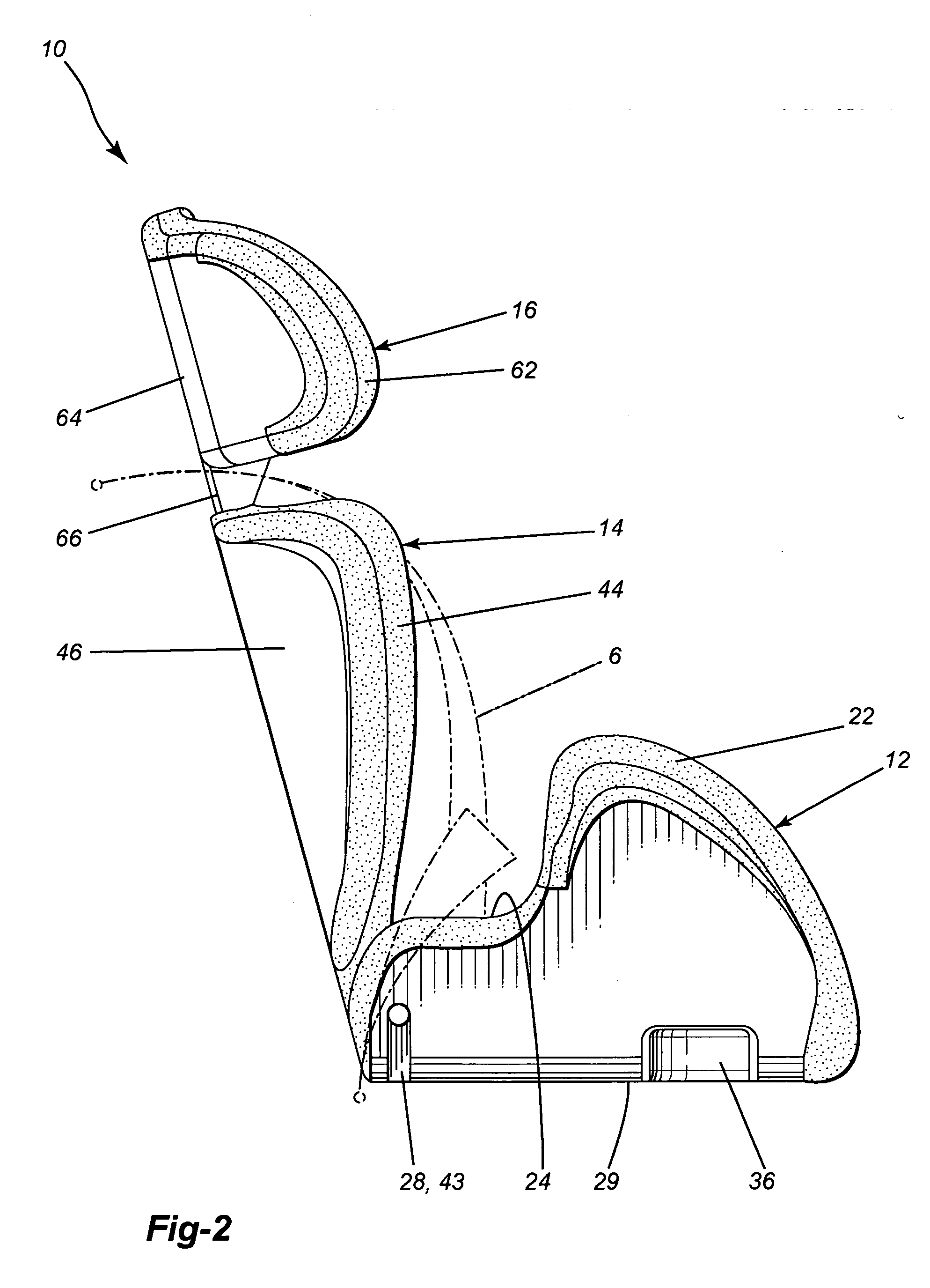
[0021] Referring now to the drawings, a preferred embodiment of a child booster seat generally indicated at 10 comprises a seat portion 12, a back portion 14, a headrest 16 and a cup holder 18. The child booster seat 10 is designed so that the seat 10 and a child seating therein are restrained on a vehicle seat by a seat belt 2 integral with the vehicle and the vehicle seat. The child booster seat 10 is designed to accommodate children generally between 3 and 12 years old, with a maximum weight capacity of 100 pounds and a maximum height of 60 inches tall.

[0022] As can be best seen in FIGS. 1 and 2, the seat portion 12 includes a seating surface 20 which is slightly curved so as to provide comfortable seating. A pair of armrests 22 extends vertically from the seating surface 20. Each armrest 22 includes a groove 24 adjacent to the back portion 14 of the seat 10 which is designed to receive a lap portion 4 of the seat belt 2. A rear end of the seat portion 12 preferably includes two...


PUM


Abstract

A child booster seat comprising a seat portion, a back portion including a cavity opening onto a top surface thereof, and a rear surface defining a slot in communication with the cavity with first retaining means adjacent thereto, and a headrest having a stem integral therewith including second retaining means and being adapted to be inserted in the cavity such as to maintain a height of the headrest by the engagement of the second retaining means with the first retaining means through the elongated slot. Also, a child seat comprising a seat portion having a bottom surface and side walls, a cup holder including a leg having fastening means, and at least one complementary fastening receptacle in the bottom surface opening in a side wall and being adapted to retain the leg, so that the cup holder can be detachably mounted in the receptacle while protruding beyond the side wall.

Description

FIELD OF THE INVENTION [0001] The present invention relates to child restraint systems for use in motor vehicles, and more particularly to a child booster seat for use in an automobile. BACKGROUND OF THE INVENTION [0002] Children between 3 and 12 years of age generally require a booster seat in order to be able to be safely restrained in a car seat. Such seats are usually designed to use a car seat belt designed for adults so that the belt can be properly positioned to restrain the child. Booster seats are traditionally molded as a rigid shell. Such booster seats present a number of disadvantages, one of which is the fact that they cannot be adjusted to allow a better fit either with the child sitting therein or with the car seat they are installed on. [0003] CA 2,300,922A1, published Mar. 4, 1999 by Reithmeier et al., shows a booster seat with an angularly adjustable back rest and a headrest which is slidably mounted onto a vertically extending guiding device integral with the back...

Claims


Application Information

Patent Timeline
Patent Type & Authority Applications(United States)
IPC IPC(8): A47D1/10B60N2/26B60N2/28B60N2/48B60N3/10
CPCB60N2/2851B60N3/108B60N3/103B60N2/4811B60N2/812
Inventor HALL, DAVIDBOURBONNAIS, RICHARD
Owner COSCO MANAGEMENT INC
Why Eureka
Try Eureka