Sample tube assemblies and methods of constructing such sample tube assemblies

a tube and sample technology, applied in the field of tubes, can solve the problems of increasing the cost, easy to achieve, and complicated identification of a specific tube, and achieve the effect of modest cost and cheap and economical printing

Inactive Publication Date: 2005-09-01
ADVANCED BIOTECHNOLOGIES LTD
View PDF8 Cites 0 Cited by
  • Summary
  • Abstract
  • Description
  • Claims
  • Application Information

AI Technical Summary

Benefits of technology

[0018] Preferably the end cap sidewall incorporates a ridge extending substantially around the circumference of the sidewall. This arrangement improves the quality and integrity of the seal between the end cap and the tube portion.
[0029] The label may also be a printed label. Printing is cheap and economical and high definition printers are now available at modest cost. Because the substrate is protected from the elements a printed paper label is acceptable.

Problems solved by technology

A typical example of this type of problem is when samples are kept in so-called cluster tubes stored in a cluster plate.
However, identification of a specific tube is more complicated when there are many tens of thousands of micro tube cluster plates held in the same storage area.
Firstly, the etchable coating must be applied to the bottom of the tube.
This is not easy to achieve and, where it has been achieved, inevitably increases the cost significantly.
Secondly, if the top coating becomes scratched slightly during manipulation of the tube, then this could alter or degrade the unique code by accident.
This could have very serious implications for an experiment and many man hours and expensive reagents could be lost in repeat experiments.
All of the above adds to the cost of the finished product.
Once again, if a spurious scratch or pit finds its way onto the bottom of the tube the unique code is lost.
In addition, the process for embedding or attaching a slug or layer of opaque material on the bottom of a small tube is not necessarily straightforward and adds significantly to the cost of the tube even before adding the cost of laser etching.

Method used


Image

  • Sample tube assemblies and methods of constructing such sample tube assemblies
  • Sample tube assemblies and methods of constructing such sample tube assemblies
  • Sample tube assemblies and methods of constructing such sample tube assemblies

Examples


Embodiment Construction

[0071] The present embodiments represent currently the best ways known to the applicant of putting the invention into practice. But they are not the only ways in which this could be achieved. They are illustrated, and they will now be described, by way of example only.

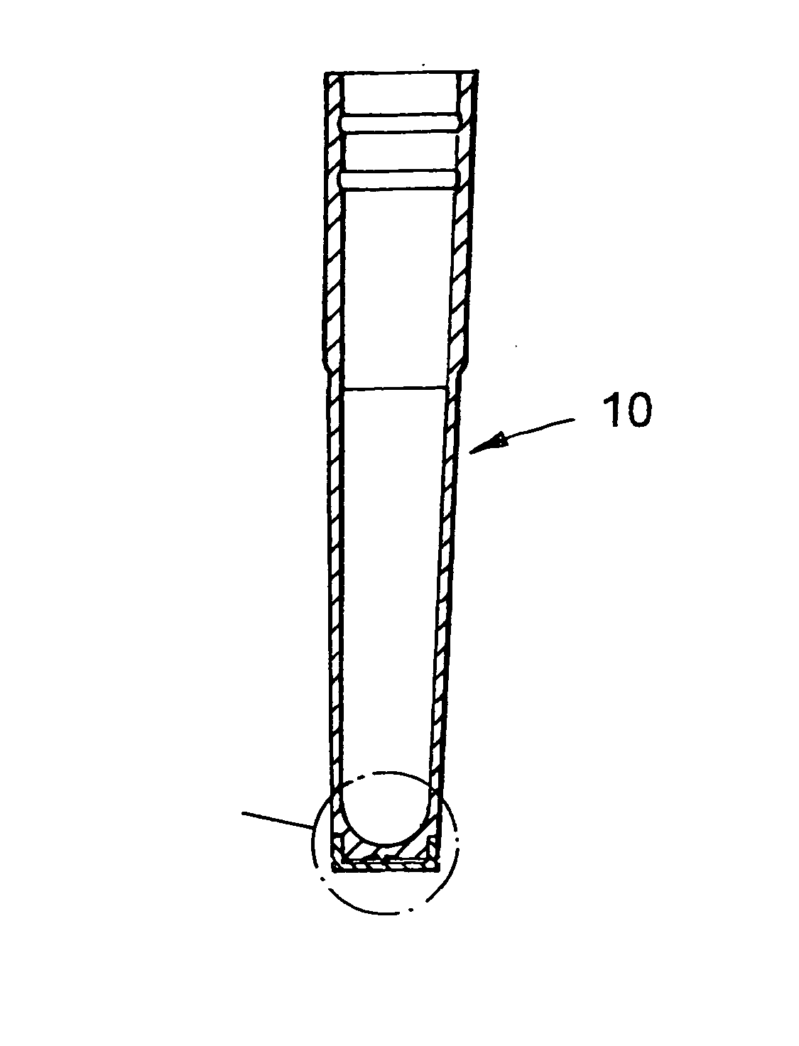
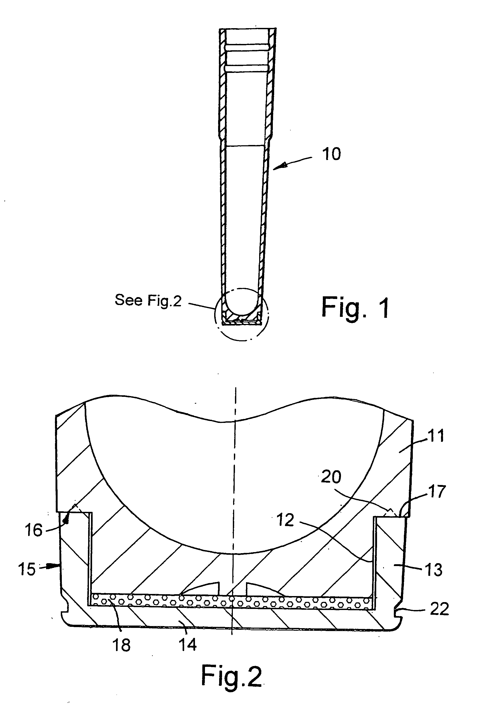
[0072]FIG. 1 illustrates a cluster tube 10 incorporating the present invention. The detail of the bottom of this cluster tube is shown more clearly in FIG. 2. Whilst the following description will show how the invention can be used in the context of a cluster tube, it will be appreciated that the invention can be applied to virtually any storage tube made of plastics material or glass.

[0073]FIG. 2 illustrates the bottom end of a tube portion 11 from a storage tube assembly generally shown as 10. The bottom end of the tube portion has a reduced diameter end region 12. Adapted to fit over this end region is a bottom end cap 13. Preferably the bottom end cap 13 is a snap fit over the reduced diameter end region 12. The ...


PUM

PropertyMeasurementUnit
lengthaaaaaaaaaa
heightaaaaaaaaaa
heightaaaaaaaaaa

Abstract

A sample tube assembly incorporating a fluid-tight label chamber, said label chamber being fused to or forming part of the body of the sample tube. The invention also includes a sample tube assembly wherein the tube assembly comprises:- (i) a tube portion, the bottom of which is adapted to accept an end cap; and (ii) an end cap adapted to be joined to the bottom of the tube portion; and (iii) a label chamber provided in use by a space between the bottom or outer surface of the bottom of the tube portion and the inner surface of the end cap; and wherein the end cap is fused, welded or otherwise joined to the bottom of the tube portion to provide a fluid tight-seal.

Description

FIELD OF THE INVENTION [0001] The present invention relates to tubes bearing a unique identifying label. It is particularly applicable, but in no way limited, to labelling storage tubes such as cluster tubes. BACKGROUND TO THE INVENTION [0002] In science laboratories there is a growing need to operate on and store increasingly large numbers of samples. These samples need to be retrieved quickly and unambiguously as and when required. Furthermore, an increasing number of laboratories are moving to robotic handling of samples. [0003] A typical example of this type of problem is when samples are kept in so-called cluster tubes stored in a cluster plate. Ideal for sample storage, a 1.2 ml micro-tube cluster plate comprises 96 individual 1.2 ml tubes held in place by a heavy duty rack in a standard microplate format. Made from polypropylene, each tube is fully supported at the base or around a collar to withstand the pressure applied by robotic systems. Caps or mats are provided to seal ...

Claims


Application Information

Patent Timeline
Patent Type & Authority Applications(United States)
IPC IPC(8): B01L3/14G01N1/10G01N35/02
CPCY10T436/13B01L3/5453
Inventor DAY, PAUL FRANCIS
Owner ADVANCED BIOTECHNOLOGIES LTD
Why Eureka
Try Eureka