Single-core self-coupled inductor device

a self-coupling, inductor technology, applied in the direction of inductances with magnetic cores, ac networks to reduce harmonics/ripples, cores/yokes, etc., can solve the problems of increasing the size of the connection of several inductances together, cost and energy inefficiency,

Inactive Publication Date: 2015-02-26
TORYTRANS
View PDF2 Cites 0 Cited by
  • Summary
  • Abstract
  • Description
  • Claims
  • Application Information

AI Technical Summary

Benefits of technology

[0016]- In is cheaper in economic terms, since it has a single core with three windings. There is a savings of two whole cores as compared to building three conventional inductances with three cores and three windings.

Problems solved by technology

In addition, connecting several inductances together generates a considerable increase in size, cost and energy inefficiency.
Depending on whether single-phase, two-phase or three-phase has been installed, this problem may also be aggravated by the fact that each phase needs its own associated set of components.

Method used


Image

  • Single-core self-coupled inductor device
  • Single-core self-coupled inductor device
  • Single-core self-coupled inductor device

Examples


Embodiment Construction

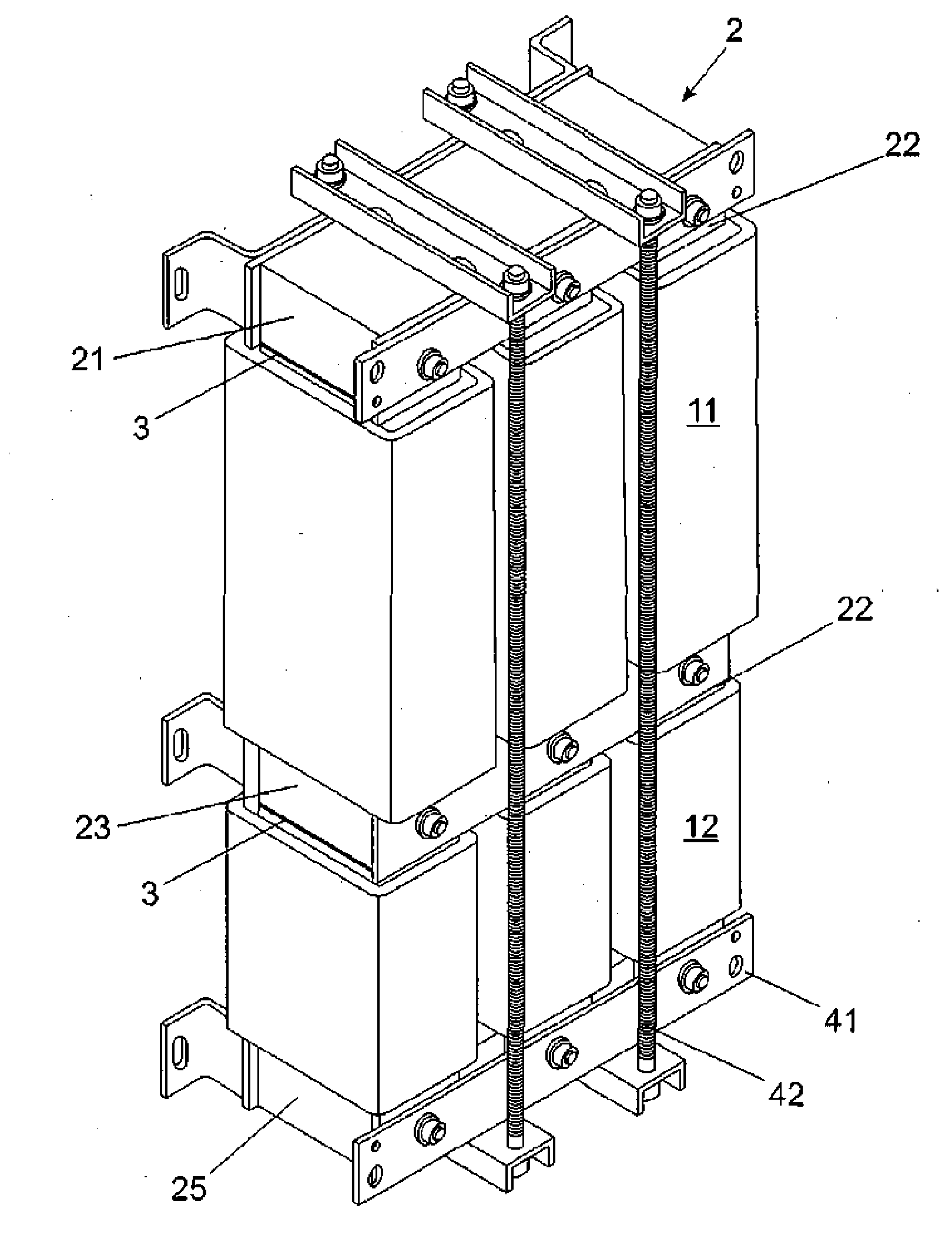
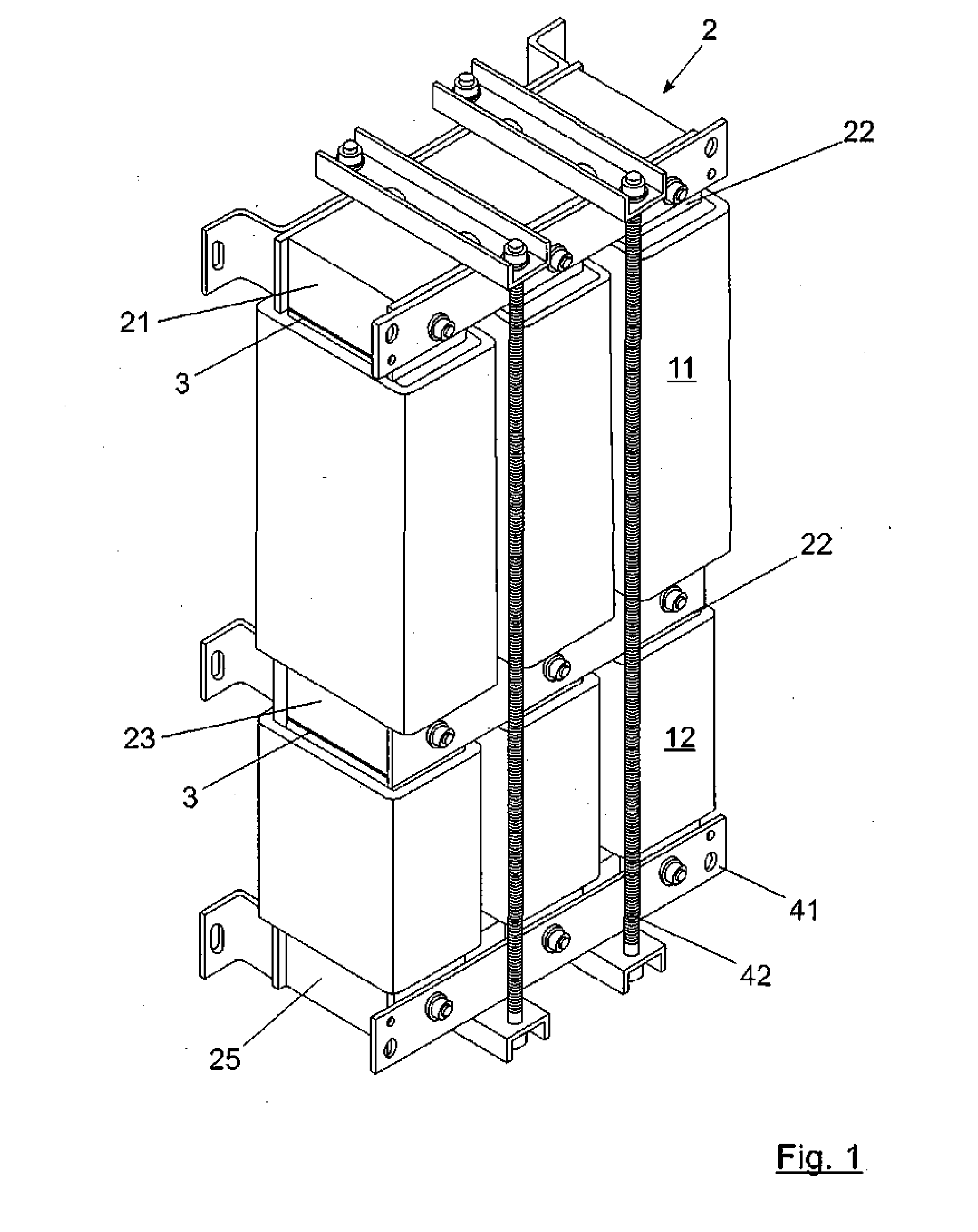
[0029]As may be observed in FIG. 1, the self-coupled inductor device encompasses all of the necessary inductances in a single element. Specifically, in the primary columns is where the coils of the primary inlet inductance (11) are located, which are wound concentrically and are therefore self-coupled with the coils of the primary outlet inductance (12). In the secondary columns the coils of the secondary inductance (13) are located, which do not share magnetic coupling with the primary coils. The single magnetic core (2) has also been represented, and a distributed gap (3), both of which are shown in greater detail in the next figure.

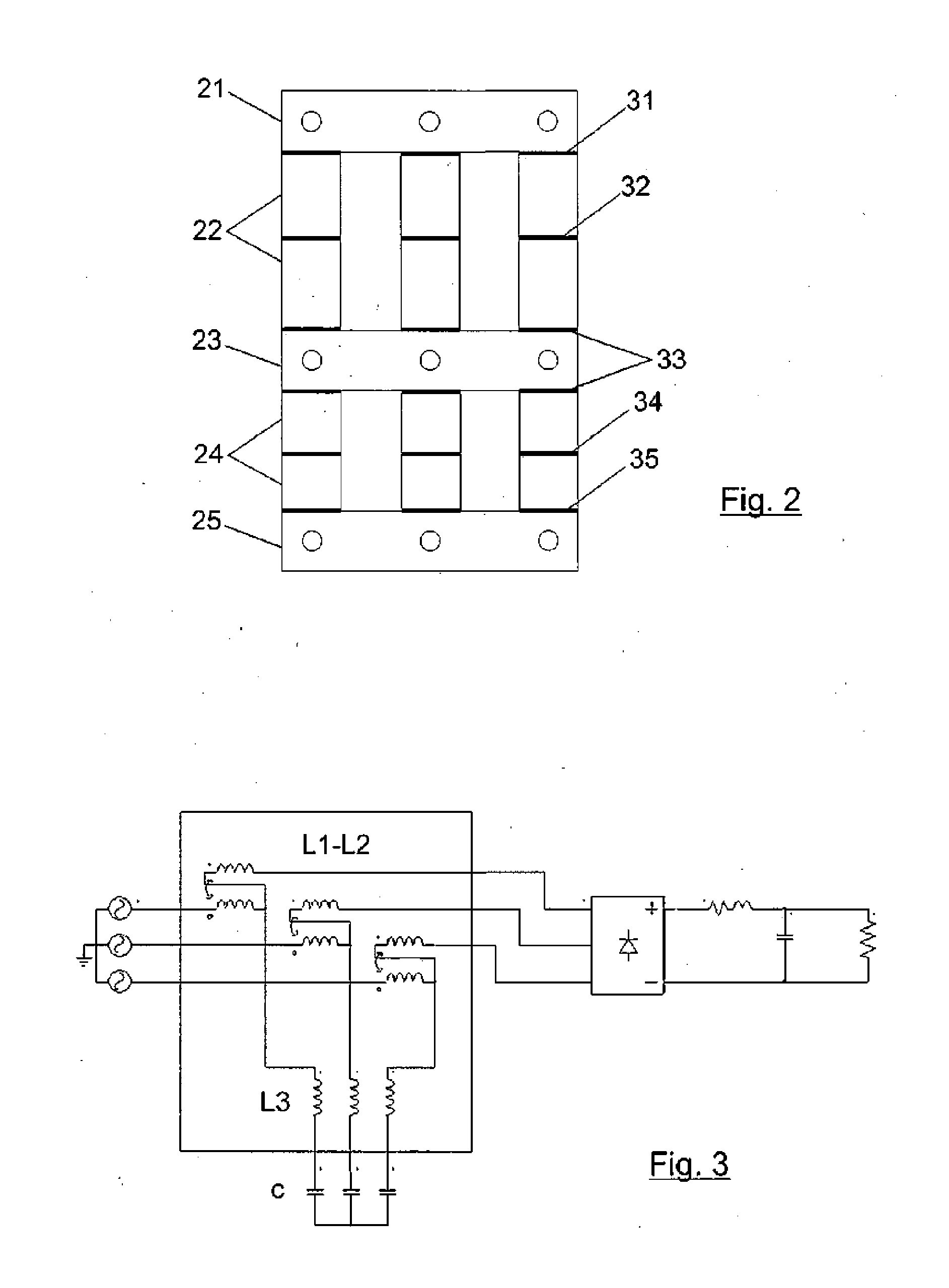
[0030]FIG. 2 shows the geometry of the single magnetic core for conducting flux, which is made up of the upper yoke (21), which closes the magnetic flux of the primary columns (22) of the windings of the primary self-coupled inlet and outlet inductances, the central common yoke (23) that closes the flux of the primary and secondary inductances, the sec...


PUM

PropertyMeasurementUnit
inductancesaaaaaaaaaa
inductanceaaaaaaaaaa
magnetic fluxaaaaaaaaaa

Abstract

Single-core self-coupled inductor that offers an advantageous distribution of gaps (3) for controlling and modifying the leakage of the magnetic flux, with at least one primary inlet inductance (11) self-coupled to a primary outlet inductance (12) and an adjacent secondary inductance (13). There is a magnetic core (2) composed of primary columns (22), a secondary column (24), an upper primary yoke (21), a lower secondary yoke (25) and a central common yoke (23).

Description

TECHNICAL FIELD OF THE INVENTION[0001]The invention relates to an single-core self-coupled inductor device that offers a novel magnetic geometry and winding arrangement and an advantageous distribution of gaps.BACKGROUND ART[0002]It is a known fact that an inductance comprises a coil that is wound around a core that has a series of gaps. The gaps modify the leakage of the magnetic flux, mainly in order to obtain a desired inductance value.[0003]In many applications, for example band-pass, band-stop, low-pass and high-pass filters, it is necessary to connect several inductances together according to their type (L-C, L-C-L, L-LC-L, etc.). The connection is made component by component and often means that some components affect the operations of others. Effects such as common mode attenuation caused by mutual inductance must be taken into account in this type of application. In addition, connecting several inductances together generates a considerable increase in size, cost and energy ...

Claims


Application Information

Patent Timeline
Patent Type & Authority Applications(United States)
IPC IPC(8): H01F3/14
CPCH01F3/14H01F27/24H01F27/385H01F37/00H02J3/01Y02E40/40
Inventor CAMBRONERO GARCIA, JOSE
Owner TORYTRANS
Why Eureka
Try Eureka