Passive haptic interface

a haptic interface and passive technology, applied in the direction of mechanical control devices, instruments, manual control with single controlling member, etc., can solve the problems of poor torque/magnet volume ratio, torque loss, size limitation of miniaturization possibilities,

Pending Publication Date: 2022-09-22
MOVING MAGNET TECH
View PDF1 Cites 0 Cited by
  • Summary
  • Abstract
  • Description
  • Claims
  • Application Information

AI Technical Summary

Benefits of technology

[0020]The present disclosure aims to overcome the drawbacks of the state of the art by allowing a more economical industrial production of the movable and fixed elements of a passive magnetized haptic interface, “passive” meaning that the haptic effect is obtained without a power supply.
[0022]It is also in the object of the present disclosure to provide a simple and economical solution in order to install a position sensor in a haptic device.
[0034]It is also in the object of the present disclosure to allow the economical production of a haptic interface. The present disclosure particularly relates to a rotary haptic interface, the first movable element comprising a ring of permanent magnets extending axially secured to a disc part, the disc part being extended axially in a direction opposite the magnets by a magnetic plate used for the position detection of the first movable element, and the second fixed element comprising a ring made from a soft ferromagnetic material extended by teeth facing the ring of permanent magnets.

Problems solved by technology

The consequence is a poor torque / magnet volume ratio.
In addition, the solutions proposed by this patent come up against a problem of size limiting the possibilities for miniaturization: when the number of protuberances formed on the metallic element becomes large, it is necessary to reduce the section of the magnet or of the pair of magnets in order to prevent the generated magnetic field from interacting with several neighboring protuberances.
However, by reducing the section of the magnet, torque is lost, and the indexing resistance is attenuated until it is no longer noticeable.
The resolution of the indexing is limited by the size of the pitches between the teeth, which must be greater than the size of the magnet.
These embodiments therefore do not allow high indexing resolutions to be achieved.
This solution is not satisfactory because it also has great stiffness and poor resolution, which is necessarily limited to the pitch of the magnets.
Furthermore, it requires a large number of magnets to produce a large number of notches.
This solution also presents industrialization difficulties, because it requires the complex assembly of small parts.
This embodiment allows only mediocre resolution because the number of notches is limited to the number of teeth that can be made, phased and aligned with the stator.
For each notch, only one rotor magnet participates in the torque; the stresses are asymmetrical and the ratio between the volume of magnets and the torque produced is poor.
When there is a need to create a large number of notches, for example seventy-two (72), over a complete rotation of the movable part (or over a given angle or linear movement), these devices of the prior art have the drawback of requiring a large number of magnets or ferromagnetic poles.
When this relatively large number of notches is coupled with a need for miniaturization, the difficulty of producing the solution on an industrial scale then becomes significant with small elements that are difficult to achieve with the set of tight tolerances to be maintained.
The devices of the prior art often use optical or magnetic sensors that are simply placed near the haptic device, making the solution either bulky or uneconomical.

Method used


Image

  • Passive haptic interface
  • Passive haptic interface
  • Passive haptic interface

Examples


Embodiment Construction

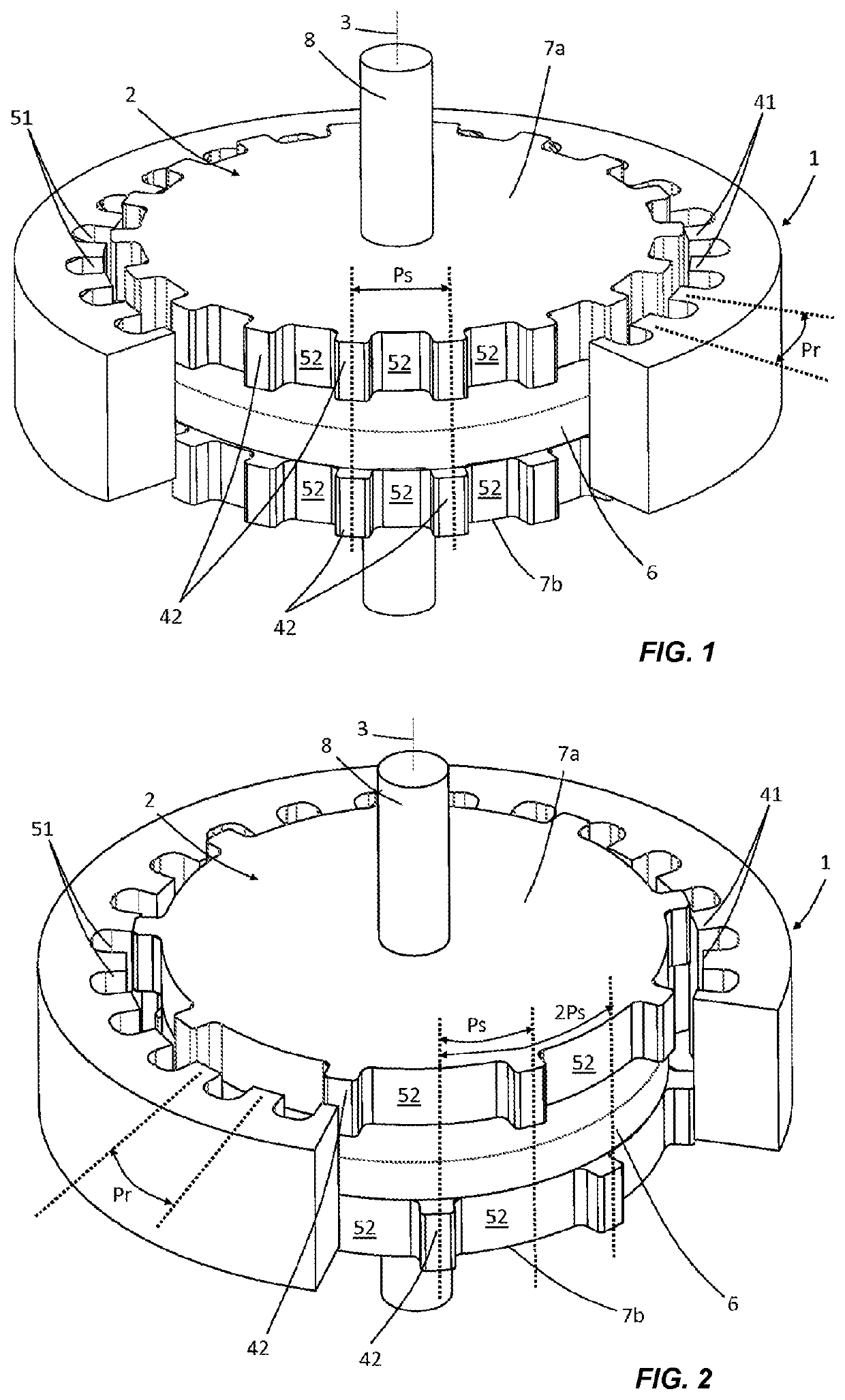
[0055]FIG. 1 shows a first embodiment of a rotary haptic interface according to the present disclosure. It comprises a first movable element (1) here in the form of a ring, the outer surface of which is cylindrical and may optionally be textured (not visible here) in order to improve the grip or digital actuation by a user. The inner surface of this movable element (1) has a succession of teeth (41), oriented radially relative to the axis (3) of rotation, and notches (51), defining a pole pitch Pr. This first movable element (1) is made from a soft ferromagnetic material, for example, a steel or an iron alloy. A second fixed element (2) is positioned inside this first movable element (1) and radially facing the first movable element (1). This second fixed element comprises a permanent magnet (6) in the form of a disc, the magnetization of which is directed axially. Positioned axially on either side of this magnet (6) are two ferromagnetic discs (7a, 7b) made from soft iron, each ext...


PUM


Abstract

A passive haptic interface includes a first element which is rotatably movable about an axis or translatably movable along an axis, the first movable element rotating or moving opposite a second fixed element. The first movable element has a first plurality of magnetic poles spaced periodically at a pole pitch Ps and in the direction of movement, and the second fixed element has a second plurality of magnetic poles periodically spaced at a pole pitch Pr and in the direction of movement, where Ps and Pr are different numbers. A periodic stress is created by the magnetic interaction between the first movable element and the second fixed element in a period Pt. The pole pitches Ps and Pr are chosen such that Pt is strictly less than the smallest of the pitches Ps and Pr.

Description

CROSS-REFERENCE TO RELATED APPLICATIONS[0001]This application is a national phase entry under 35 U.S.C. § 371 of International Patent Application PCT / FR2020 / 051444, filed Aug. 6, 2020, designating the United States of America and published as International Patent Publication WO 2021 / 023951 A1 on Feb. 11, 2021, which claims the benefit under Article 8 of the Patent Cooperation Treaty to French Patent Application Serial No. 1909057, filed Aug. 7, 2019.TECHNICAL FIELD[0002]The present disclosure relates to a passive haptic interface, that is to say, one that can be manipulated by the finger or the hand, possibly even by the foot of a user, and providing a felt variable stress without power consumption.[0003]The present disclosure applies to, for example, an office automation computer control interface or to a control interface inside a motor vehicle or else to a control interface of a household appliance.BACKGROUND[0004]Manual haptic devices are known using a magnetic interaction betwe...

Claims


Application Information

Patent Timeline
Patent Type & Authority Applications(United States)
IPC IPC(8): G05G5/03G05G5/06G05G9/047G05G1/08H01H19/11
CPCG05G5/03G05G5/06G05G9/047G05G1/08H01H19/11G05G2009/04707G05G2009/04781G06F3/0362H01H2003/506
Inventor ALZINGRE, JEAN-DANIELFOUCOUT, ANTOINEPAJOT, OLIVIER
Owner MOVING MAGNET TECH
Why Eureka
Try Eureka