
A Composite Machining Method for Gas Film Hole of Guide Vane

A guide vane and composite machining technology, which is applied in the field of composite machining of air film holes of guide vanes, can solve the problems of affecting the safety and reliability of the vane, low absorption rate, difficult processing, etc., so as to improve the aperture qualification rate, processing efficiency, and oxidation resistance. and high temperature resistance, avoiding the effect of poor hole forming quality

Active Publication Date: 2020-12-25
AECC AVIATION POWER CO LTD
View PDF10 Cites 0 Cited by
  • Summary
  • Abstract
  • Description
  • Claims
  • Application Information

AI Technical Summary

Problems solved by technology

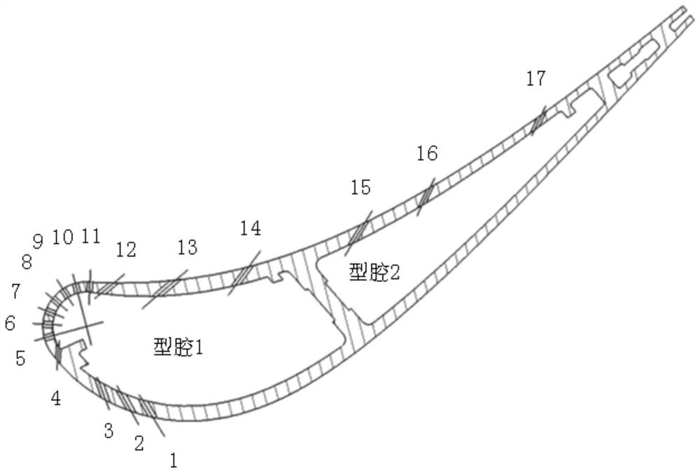
[0003] A certain type of aero-engine high-pressure turbine guide vane material is Ni 3 Al-based IC10 directionally solidified superalloy, the blade body and the upper and lower edge plates are integrally cast without allowance, the structure is complex, and more than 600 apertures and space angles are distributed on the curved surface contours of the blade body and upper and lower edge plates. The air film holes on the air inlet side of the blade body are very dense and difficult to process
At the same time, Ni 3 The Al-based alloy IC10 material has an aluminum content as high as 6.5-9.0%, and aluminum metal has a low absorption rate for laser light. The laser is difficult to process and the metal spatter produced is easy to adhere to the surface of the part. Mechanical grinding is required to remove the surface of the part. The removal of metal spatter will damage the surface quality of parts and affect the safety and reliability of blades

Method used


Image

  • A Composite Machining Method for Gas Film Hole of Guide Vane
  • A Composite Machining Method for Gas Film Hole of Guide Vane

Examples


Embodiment Construction

[0029] The present invention will be described in further detail below in conjunction with the accompanying drawings.

[0030] The present invention is aimed at Ni 3 Al-based IC10 directionally solidified high-temperature alloy material, blade body and upper and lower edge plates are integrally cast without allowance, new material and new structure aero-engine high-pressure turbine guide vane, and a method for machining gas film holes by laser-electric spark composite processing is provided. Specifically, it can be achieved through the following measures:

[0031] Apply anti-splash agent: It has been verified by the process that the hexagonal boron nitride water-based coating is suitable as an anti-splash agent for laser processing air film holes, and the material has no effect on the part matrix material during processing. Hexagonal boron nitride and graphite are isoelectronics. It has a layered structure similar to graphite, and has good lubricity, electrical insulation, th...


PUM

PropertyMeasurementUnit
thicknessaaaaaaaaaa
anti-oxidation temperatureaaaaaaaaaa

Abstract

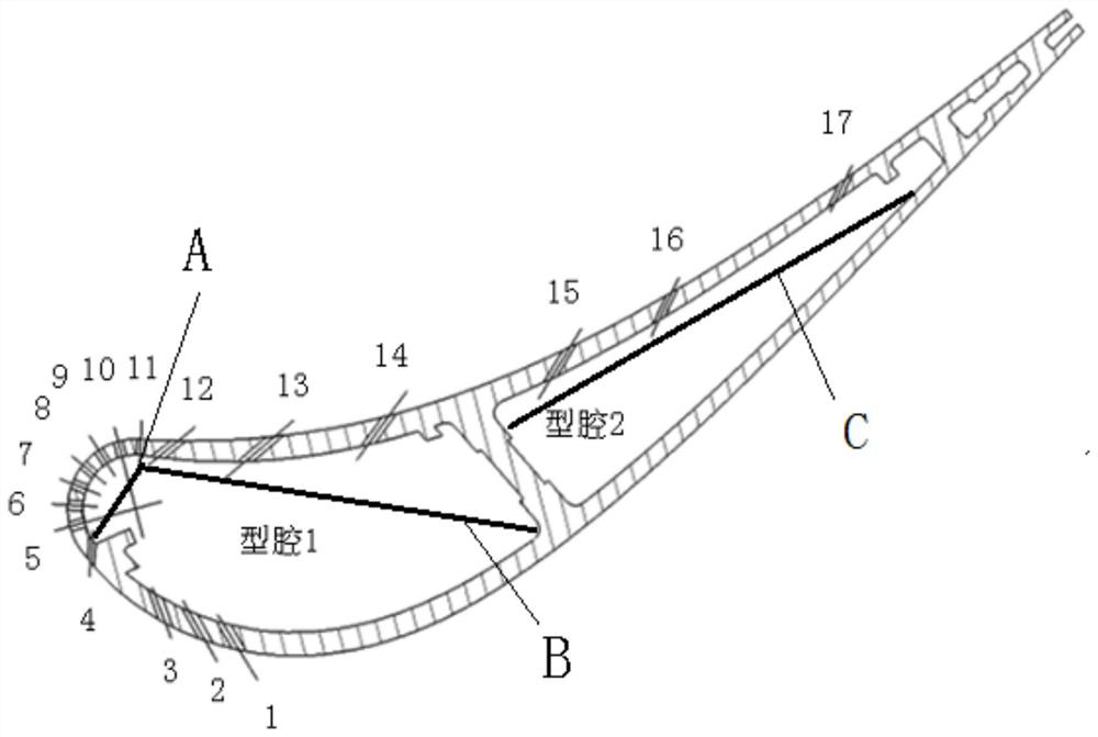
The invention relates to a guide vane air film hole composite machining method which comprises the steps that the surface and a cavity of a to-be-machined high-pressure turbine guide vane are coated with an anti-splashing agent, and the high-pressure turbine guide vane with an anti-splashing coating is obtained through drying; to-be-machined air film holes are located in a blade body and an edge plate of the high-pressure turbine guide blade correspondingly, and the to-be-machined air film holes in the blade body comprise the first air film hole and the second air film hole. A protection plateis placed in a cavity of the blade, the first air film hole and the second air film hole in the blade body are machined through electric sparks, the rest air film holes in the blade body and the airfilm holes in the edge plate are machined through lasers, and laser-electric spark composite machining of the air film holes of the high-pressure turbine guide blade is completed through aftertreatment. The protection plate is adopted for protection and partial machining, the problems that the wall is damaged by the hollow blade and metal splashes are discharged are solved, the percent of pass ofair film hole diameters and the machining efficiency are greatly improved, and the surface quality integrity of parts is improved through an anti-splashing agent.

Description

technical field [0001] The invention relates to the field of aero-engine manufacturing, in particular to a composite processing method for air film holes of guide blades. Background technique [0002] As the thrust and thrust-to-weight ratio of aeroengines continue to increase, the temperature at the outlet of the combustion chamber is getting higher and higher, which leads to an increase in the operating temperature of the engine blades. Machining film cooling holes on the working blades and guide blades of aeroengine turbines is an effective way to reduce the surface temperature of the turbine blades, thereby increasing the temperature before the turbine and increasing the thrust-to-weight ratio of the engine. There are a large number of air film holes distributed on the surface of the turbine cooling blade of the aero-engine, which are used to cool the blade. The diameter of these air film holes is generally 0.5-0.8mm, the space angle is complicated, and the processing i...

Claims


Application Information

Patent Timeline
Patent Type & Authority Patents(China)
IPC IPC(8): B23H5/04
CPCB23H5/04
Inventor 王辉明朱红钢耿军儒李文涛魏颖王亚东张文才张超
Owner AECC AVIATION POWER CO LTD
Learn More