
Sensor, magnetostrictive element, assisted bicycle and method for producing magnetostrictive element

Inactive Publication Date: 2005-09-15
TDK CORPARATION
View PDF3 Cites 13 Cited by
  • Summary
  • Abstract
  • Description
  • Claims
  • Application Information

AI Technical Summary

Benefits of technology

[0015] A power can be stabilized less sensitive to temperature change by keeping the compositional ratio x of Tb contained in the magnetostrictive element at 0.50<x≦1.00.
[0021] The present invention provides a sensor comprising a magnetostrictive element whose inductance changes to a limited extent with varied temperature to stably generate power by keeping the compositional ratio x of Tb contained in the magnetostrictive element at 0.50<x≦1.00. The sensor allows an assisted bicycle in which it is used to stably keep a generated auxiliary force, because of suppressed changes in auxiliary force with ambient conditions.

Problems solved by technology

When applied to torque sensors, however, the above magnetostrictive element composition involves problems such that magnetostrictive properties becomes unstable as temperature changes.
), with the result that the electrical signal generated in response to applied pedal pressure becomes unstable with temperature.
The torque sensor, when used for electric hybrid bicycles, causes unfavorable phenomena, e.g., a smaller auxiliary force is generated at the same magnitude of pedal pressure, depending on ambient temperature conditions.

Method used


Image

  • Sensor, magnetostrictive element, assisted bicycle and method for producing magnetostrictive element
  • Sensor, magnetostrictive element, assisted bicycle and method for producing magnetostrictive element
  • Sensor, magnetostrictive element, assisted bicycle and method for producing magnetostrictive element

Examples


example 1

[0062] The temperature characteristics of the magnetostrictive element 11, produced by the above-described method, were evaluated, where the compositional ratio x of Tb in the alloy composition represented by Formula (2) TbxDy(1-x) was varied, as described below.

[0063] Each magnetostrictive element 11 sample had the following compositional ratio x of Tb: [0064] Condition 1: x=0.28, Alloy composition: Tb0.28Dy0.72Fe1.875 [0065] Condition 2: x=0.30, Alloy composition: Tb0.30Dy0.70Fe1.875 [0066] Condition 3: x=0.32, Alloy composition: Tb0.32Dy0.68Fe1.875 [0067] Condition 4: x=0.34, Alloy composition: Tb0.34Dy0.66Fe1.875 [0068] Condition 5: x=0.40, Alloy composition: Tb0.40Dy0.60Fe1.875 [0069] Condition 6: x=0.60, Alloy composition: Tb0.60Dy0.40Fe1.875 [0070] Condition 7: x=1.00, Alloy composition: Tb1.00Fe1.875

[0071] Magnetostrictive elements 11, having the respective compositions shown above in the conditions 1 to 7, were rod-shaped (columnar), 7.4 mm in diameter and 3 mm in length....

example 2

[0079] The magnetostrictive elements 11 were produced in the same manner as in Example 1, except that the above Starting Materials A, B and C were weighed and mixed with each other to have compositions as shown below (Conditions 8 to 11). Table 1 shows the temperature characteristic coefficient P obtained for ΔL80 and ΔL240 at each of Conditions 8 to 11. [0080] Condition 8: x=0.60, Alloy composition: Tb0.60Dy0.40Fe1.5 [0081] Condition 9: x=0.60, Alloy composition: Tb0.60Dy0.40Fe3.0 [0082] Condition 10: x=0.70, Alloy composition: Tb0.70Dy0.30Fe1.875

[0083] Condition 11: x=0.90, Alloy composition: Tb0.90Dy0.10Fe1.875

TABLE 1TemperatureTemperaturecharacteristiccharacteristiccoefficient Pcoefficient Pobtained for ΔL80obtained for ΔL240Condition 80.00060.0012Condition 90.00070.0015Condition 100.00050.0010Condition 110.00040.0010


PUM

PropertyMeasurementUnit
Pressureaaaaaaaaaa
Stabilityaaaaaaaaaa
Magnetostrictionaaaaaaaaaa

Abstract

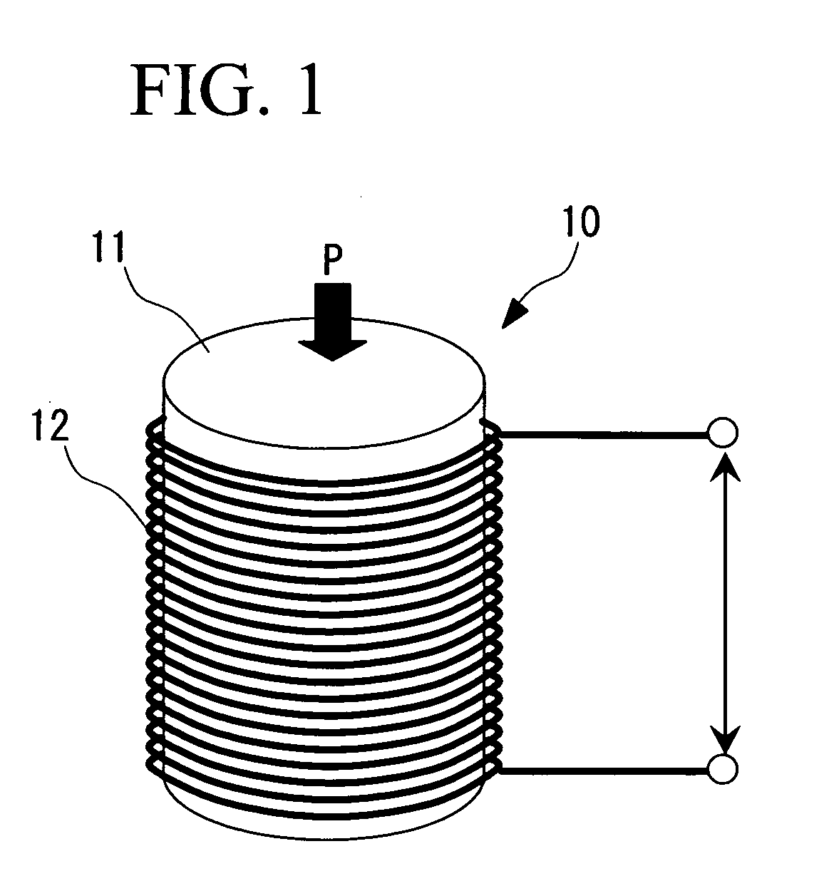
It is an object of the present invention to provide a sensor, a magnetostrictive element or the like having temperature stabilities. The sensor of the present invention for sensing a pedal pressure in an electric hybrid bicycle comprises a magnetostrictive element and a coil arranged on the outer circumferential side of the element, wherein the element is composed of a sintered body having a composition represented by TbxDy(1-x)Ty, wherein x is in the range: 0.50<x≦1.00, T represents one or more transition metal elements, and y is in the range: 1<y<4. The sensor of the above structure has temperature stabilities. The electric hybrid bicycle can stably generate an auxiliary force, when incorporated with the torque sensor.

Description

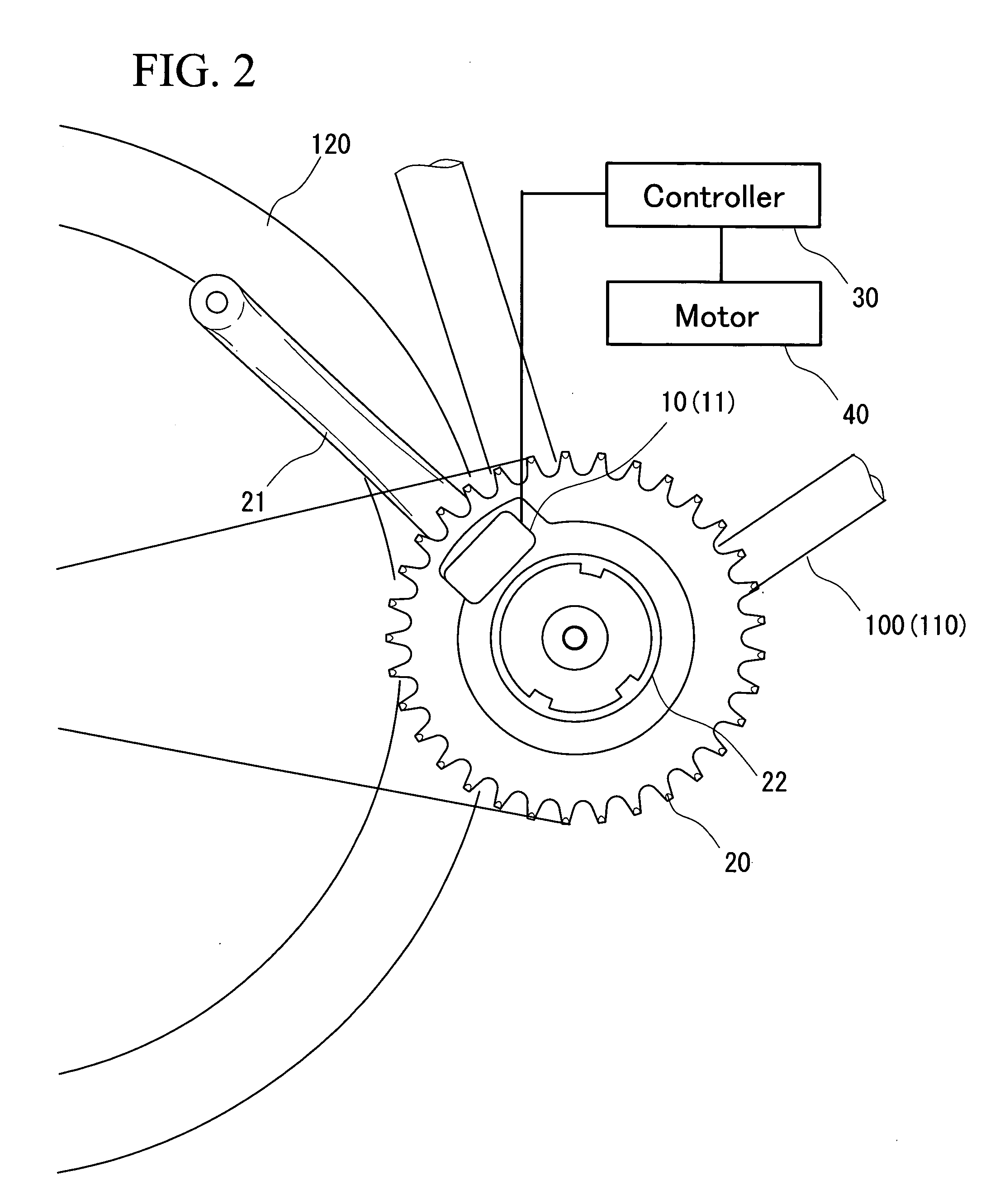
BACKGROUND OF THE INVENTION [0001] 1. Field of the Invention [0002] The present invention relates to a sensor suitable for a torque sensor used in electric hybrid bicycles, a magnetostrictive element, and an assisted bicycle or the like which uses the magnetostrictive element. [0003] 2. Description of the Related Art [0004] Recently, electric hybrid bicycles have been coming into wide use, where a motor generates an auxiliary force in response to a pedal pressure to assist in driving the bicycle. When the pedal of such an electric hybrid bicycle is pushed down by a user, the pedal pressure is sensed by a torque sensor. Based on the results, a motor generates corresponding auxiliary forces. [0005] The torque sensor for these bicycles is required to be compact, light and highly responsive. Therefore, a supermagnetostrictive element (hereinafter referred to as magnetostrictive element), which shows a much higher response speed than a conventional piezoelectric element (e.g., refer to K...

Claims


Application Information

Patent Timeline
IPC IPC(8): G01L1/12B22F3/00B62M6/45B62M6/50B62M6/55C22C1/04C22C9/00C22C18/00C22C19/00C22C21/00C22C38/00G01L3/02H01L41/20
CPCB62M6/50C22C1/02C22C28/00C22C2202/02H01L41/20G01L1/125G01L3/1435H01F1/0555H01L41/125C22F1/16H10N35/101H10N35/85
Inventor TOKORO, SEIGOMORI, TERUO
Owner TDK CORPARATION
Learn More