Security apparatus for vending machines

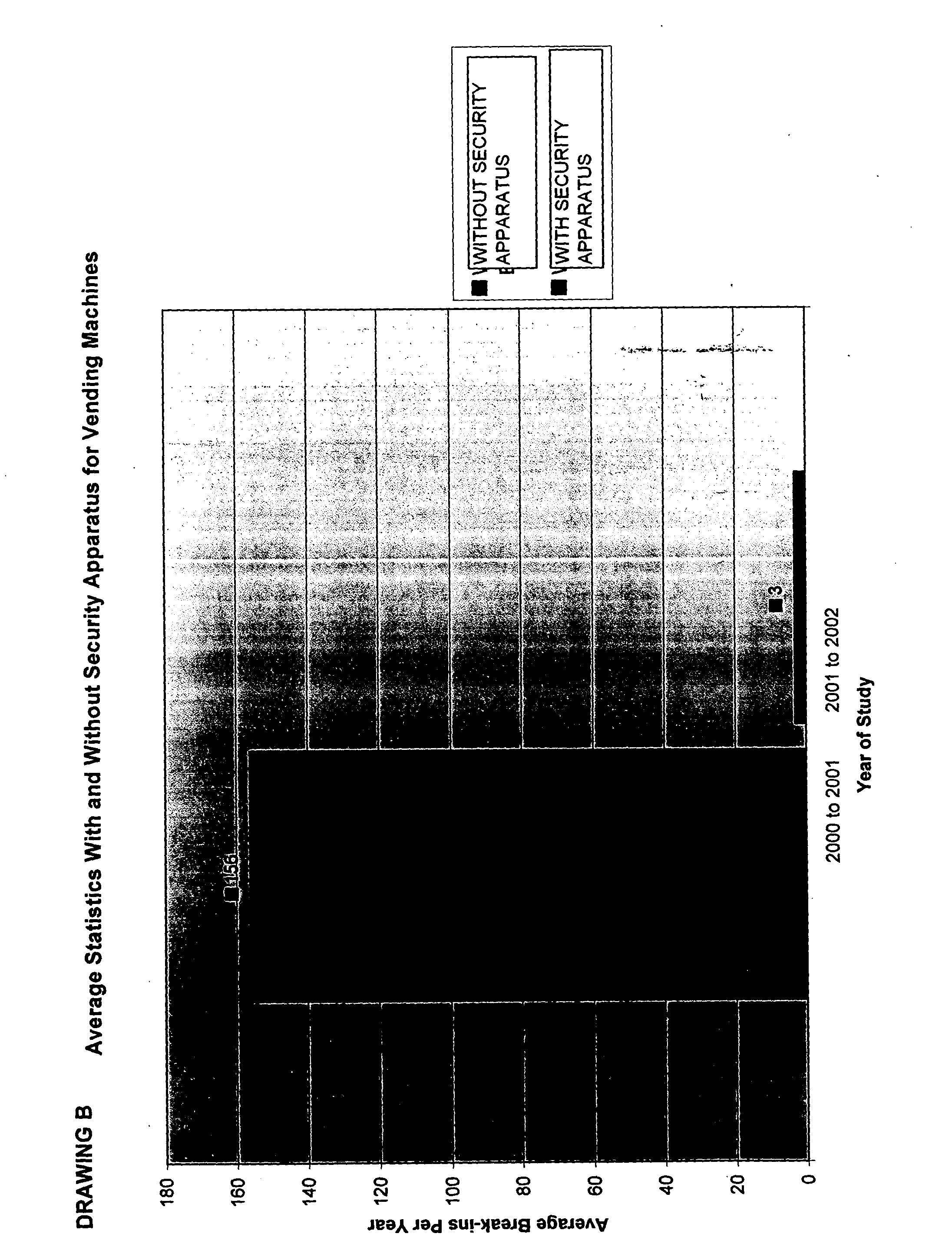
a technology for security apparatus and vending machines, applied in the direction of wing knobs, building locks, construction, etc., can solve the problems of loss of revenues, reduced available capital, and associated property damage, and achieve the effect of increasing security of vending machines and minimizing th

Inactive Publication Date: 2005-09-15
PILGRIM GEORGE EDWARD
View PDF0 Cites 1 Cited by
  • Summary
  • Abstract
  • Description
  • Claims
  • Application Information

AI Technical Summary

Benefits of technology

[0016] This invention relates to the apparatus hardware, the use of the hardware, and integrated hardware solutions for protection of vending machines by those businesses or individuals needing an effective solution to minimize theft and increase security of vending machines from theft or property damage.

Problems solved by technology

Throughout history, theft has been one of the largest causes of lost revenues, decreased available capital, and associated property damage.
Although theft occurs within all industries and markets, vending businesses are particularly hard-hit because not only is money lost, but there is almost always some associated property damage, vandalism, or destruction that can become so prevalent as to lead to bankruptcy of the business.
When theft occurs on a machine numerous outcomes cause lost revenues or increased expenses.
Examples of lost revenues or increased expenses include: (1) stolen product; (2) stolen money; (3) stolen or damaged vending machine or the machine's component parts (hinges, dollar bill holder, changer, and change bucket); (4) repair costs to the machine and its parts; (5) disappointed customers; (6) the repair or replacement down time when revenue can not be generated; and (7) costs for guard dogs, security systems, or security personnel to protect the machines in off-hours or vulnerability periods.

Method used


Image

  • Security apparatus for vending machines
  • Security apparatus for vending machines
  • Security apparatus for vending machines

Examples


Embodiment Construction

[0023] This invention relates to the development of a solution to the security problem described, it has high utility and thus meets such a requirement according to patent law.

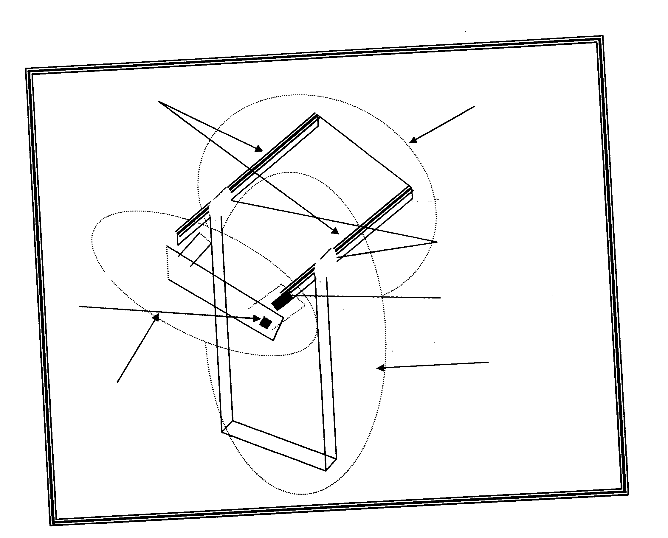
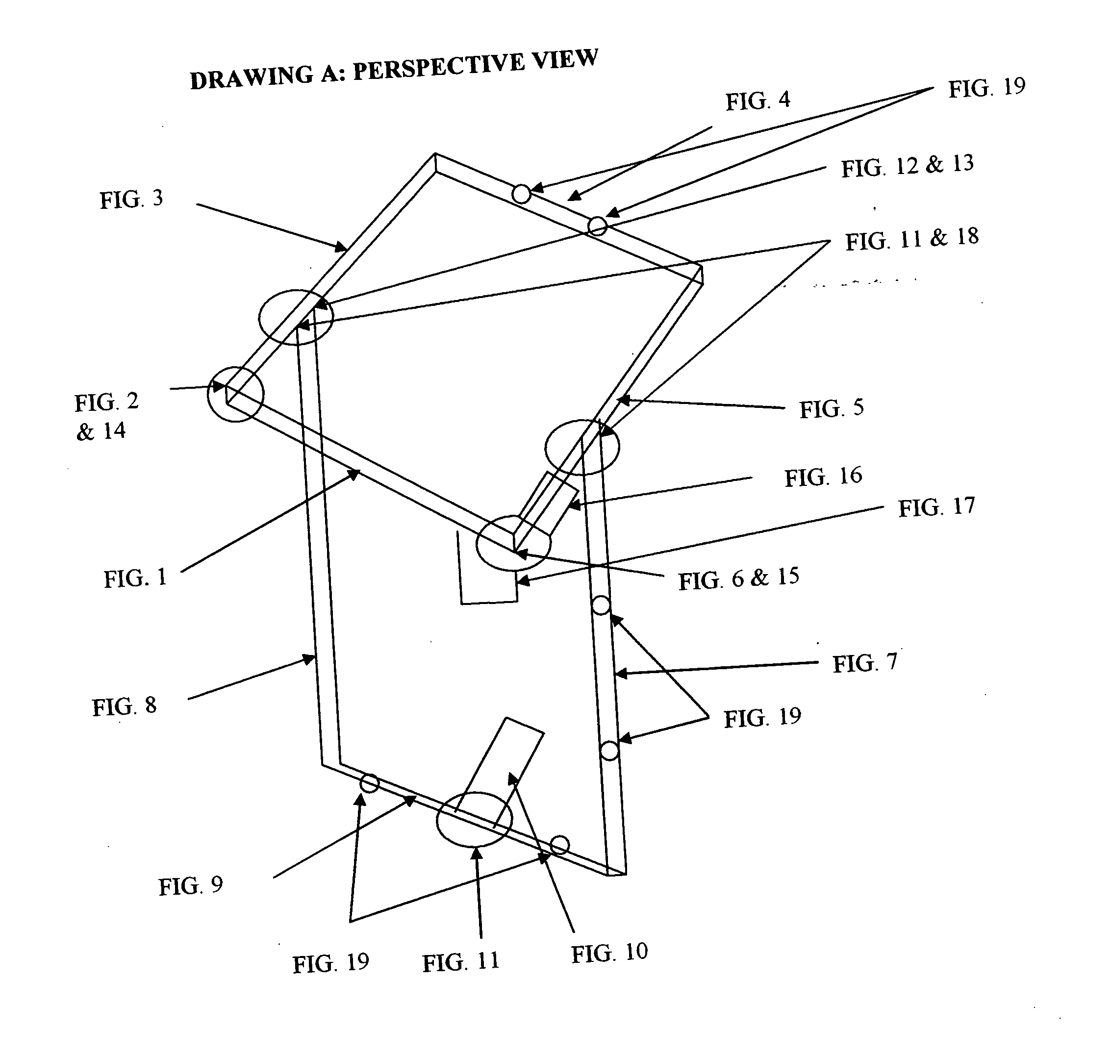
[0024] The invention includes top pieces, side pieces, shields, hinges, swivel components, fastening devices, holes and lock components as illustrated in Drawing A and Photograph 1.

[0025] The apparatus may be customized such that the device fits specific vending machine configurations, as another rendition of the invention.

[0026] The invention overcomes the specific requirement to protect a machine with security personnel, security systems, or guard animals.

[0027] The invention overcomes the specific requirement to protect a machine by encasing it in a protective cage or other similar device.

[0028] This invention is an apparatus that is installed around a vending machine unit and is dedicated to that unit and may be stabilized by attachment to a wall or floor or both.

[0029] This invention relates to a me...


PUM


Abstract

The security appartus for vending machines defined herein protects the machine from theft of the money and product contained within and deters vandalism; The vending machine is protected by a device that goes around (horizontally) and under the machine (vertically). All four sides and bottom are encased where the vertical piece supports the horizontal strap. The front of this device has a hinging guard bar with a place to put a lock on the opposite side of hinge. This device does not have to attach to the machine; therefore, no holes are drilled into machine; Yet, if preferred, the device has hole(s) for optional attachment(s) to another machine, wall or floor. This device can have optional features to added strength and security of the device such as a shield around the hinges, a shield around the lock, additional tubing around any part of the device, and a shield that protects the housing of the money contained within. The device can pivot and lock into an upright position or can be disassembled for shipping and storing purposes; and it can be installed by unlocking from the upright position and rotating the horizontal framework to the back of the machine. This device is economical, practical and easy to install and solves problems associated with vending machine theft.

Description

CROSS-REFERENCE TO RELATED APPLICATIONS [0001] This is a utility patent application that follows on Provisional Patent Nos. 60 / 425,390 and 60 / 370,211. The Inventor is George Pilgrim with an address at 3222 Tree Grove, San Antonio, Tex. 78247. STATEMENT REGARDING FEDERALLY SPONSORED RESEARCH OR DEVELOPMENT [0002] No parts of this product's development included research sponsored by any government agency. REFERENCE TO A SEQUENCE LISTING, A TABLE, OR A COMPUTER PROGRAM LISTING COMPACT DISC APPENDIX [0003] Not applicable BACKGROUND OF THE INVENTION [0004] Throughout history, theft has been one of the largest causes of lost revenues, decreased available capital, and associated property damage. [0005] Although theft occurs within all industries and markets, vending businesses are particularly hard-hit because not only is money lost, but there is almost always some associated property damage, vandalism, or destruction that can become so prevalent as to lead to bankruptcy of the business. ...

Claims


Application Information

Patent Timeline
Patent Type & Authority Applications(United States)
IPC IPC(8): E05B1/00G07F9/10
CPCG07F9/10
Inventor PILGRIM, GEORGE EDWARD
Owner PILGRIM GEORGE EDWARD
Why Eureka
Try Eureka