Telescopic flashlight

a telescopic and flashlight technology, applied in the direction of electric lighting with batteries, lighting and heating devices, lighting support devices, etc., can solve the problems of difficulty in arbitrarily controlling the lighting direction, limited use of flashlights,

Inactive Publication Date: 2005-09-15
AIKAWA TAKAMINE +1
View PDF3 Cites 47 Cited by
  • Summary
  • Abstract
  • Description
  • Claims
  • Application Information

AI Technical Summary

Benefits of technology

[0011] The cap member can be fit in the butt end of the telescopic arm member to keep it therein wh

Problems solved by technology

However, any of the conventional telescopic flashlights is constructed such that only the lighting member is allowed to be extended or shortened, so that there is a disadvantage in that the use thereof is limited to only illuminate a dark place.
Thus, wh

Method used


Image

  • Telescopic flashlight
  • Telescopic flashlight
  • Telescopic flashlight

Examples


Embodiment Construction

[0038] Hereinafter, preferred embodiments of the telescopic flashlight in accordance with the present invention will be described with reference to the attached figures.

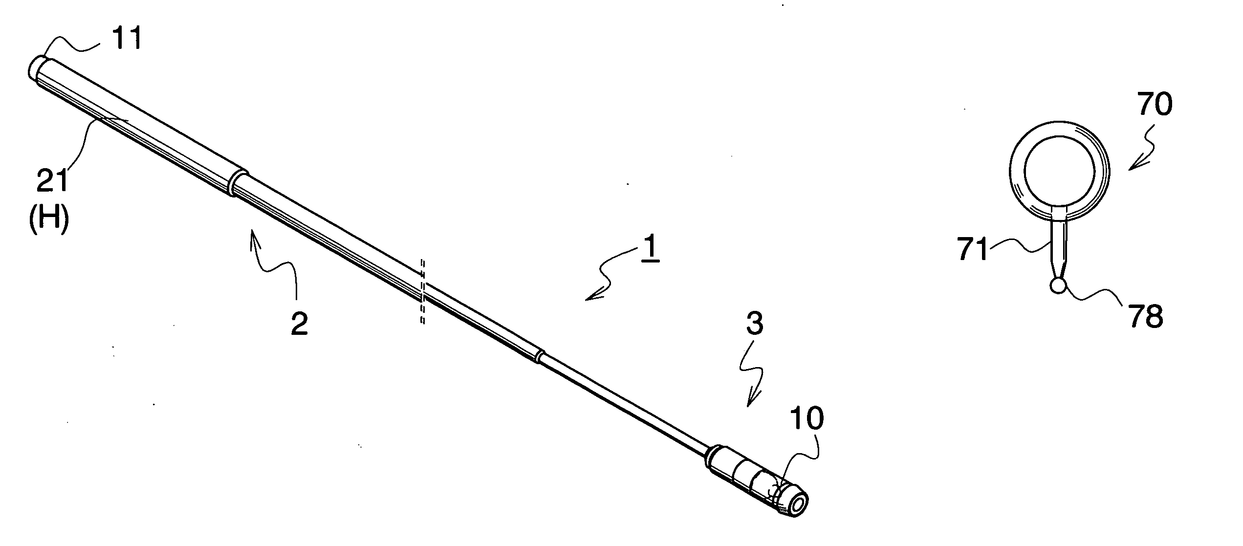
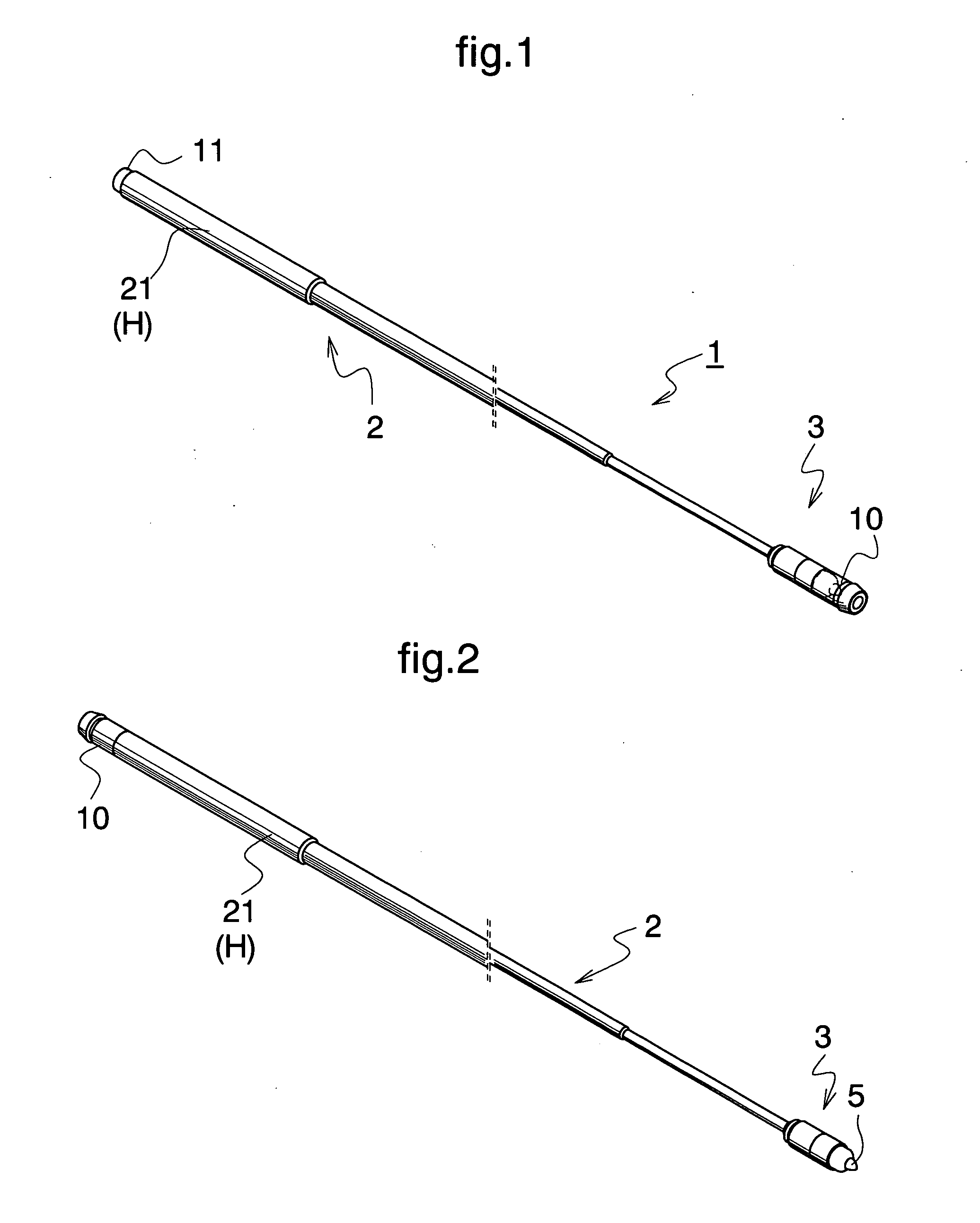
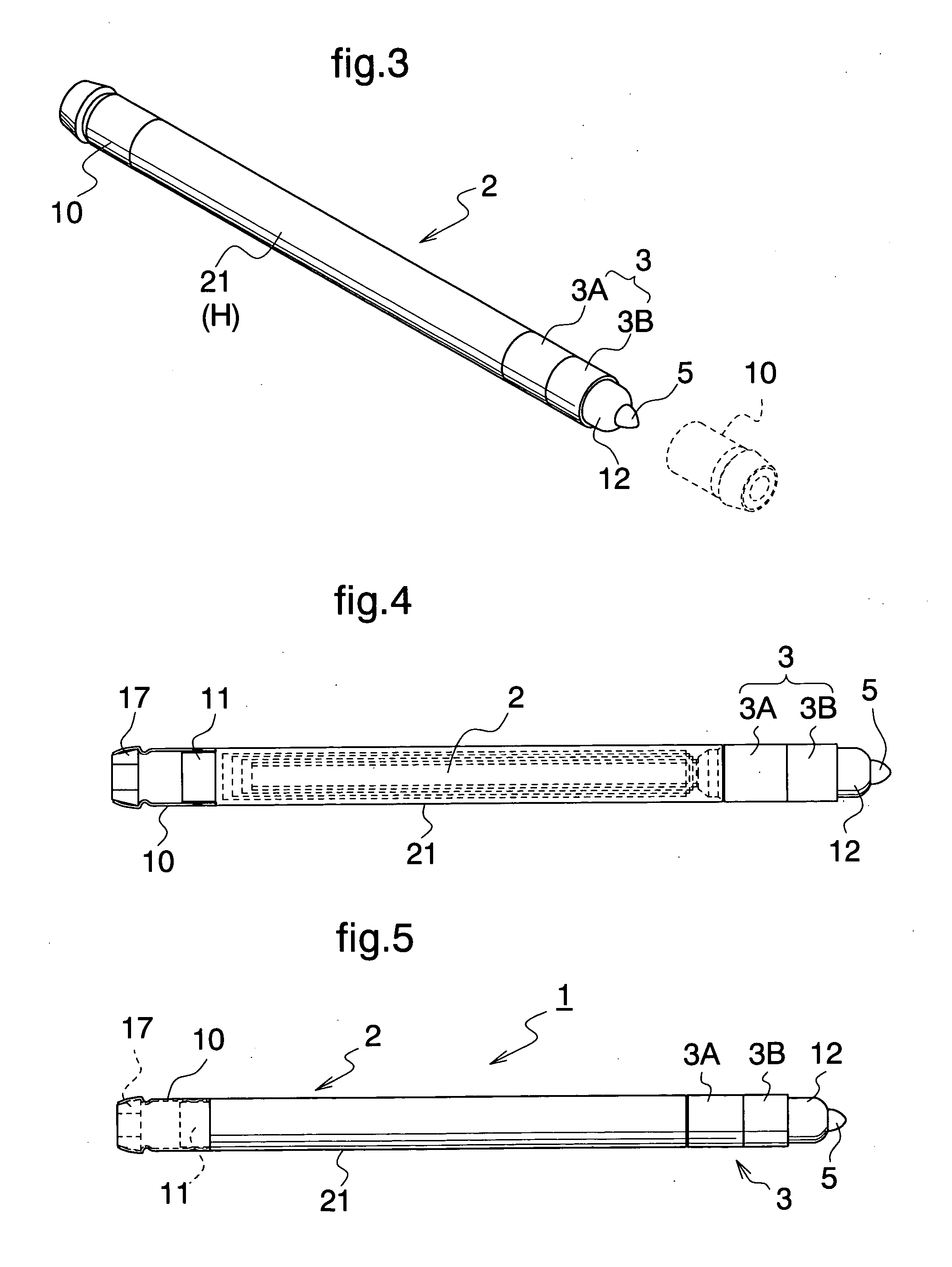
[0039] In each of FIGS. 1 to 6, there is shown a telescopic flashlight 1 as one of the preferred embodiments of the invention. The telescopic flash light 1 is made of stainless steel and is constructed of a telescopic arm member 2, a lighting member 3 mounted on the tip of the telescopic arm member 2, and a cap member 10 removably attached on the lighting member 3.

[0040] The telescopic arm member 2 is provided as a telescopic rod made of cylindrical sections (e.g., six sections) that fit or slide into each other so that it can be made longer or shorter. The outermost cylindrical section 21 is used as a holding member H. As shown in the figure, the bottom end (butt end) portion of the outermost cylindrical section 21 has a stepped portion from which a first cap-attaching portion 11 is formed such that the diameter o...


PUM


Abstract

A telescopic flashlight of the present invention is constructed such that a light-emitting part having a power supply and a lighting member is mounted on the tip of a telescopic arm member, and a cap member in the shape of a cap is detachably mounted on the tip of the light-emitting part, and a magnet, a lens, or the like is attached to the cap member and is designed to be fit to the butt end of the telescopic arm member when it is not used. In addition, a mirror, a magnifying lens, or the like may be attached to the external side of the cap member.

Description

BACKGROUND OF THE INVENTION [0001] 1. Field of the Invention [0002] The present invention relates to an improvement on a telescopic flashlight provided with a lighting member on the tip of a telescopic arm member. [0003] 2. Description of the Prior Art [0004] Conventionally, there have been proposed various configurations of a flashlight having a lighting member on the tip of a telescopic arm member to allow the light member to be extended or shortened. [0005] Concrete examples, which have been disclosed, include: a flashlight that comprises a power-supply housing part where a power-supply such as a battery or a secondary cell is housed, a telescopic arm member mounted on the power-supply housing part in a connected row arrangement, and an external lighting member mounted on the tip of the telescopic arm member and provided with electric power from the power supply (JP 09-237501 A); and a flashlight in which both an electric-supply member and a lighting member are mounted on the tip...

Claims


Application Information

Patent Timeline
IPC IPC(8): F21L4/04
CPCF21L4/045F21V21/0965F21V21/0885
Inventor AIKAWA, TAKAMINEOYA, KIKUO
Owner AIKAWA TAKAMINE
Why Eureka
Try Eureka