Modular integral magnifier

a module-integral magnifier and magnifier technology, applied in the field of modules-integral magnifiers, can solve the problems of not being popular, not being created by a stereoscopic process, and not being continuous,

Inactive Publication Date: 2006-02-21
KREMEN STANLEY H
View PDF4 Cites 50 Cited by
  • Summary
  • Abstract
  • Description
  • Claims
  • Application Information

AI Technical Summary

Problems solved by technology

However, they are not currently popular.
The lenticular stereogram, being created by a stereoscopic process, could not provide a viewer with a sense of parallax.
However, it was not continuous.
Prolonged viewing of three-dimensional pictures produces eye strain and headaches for the viewer.
This is an unnatural viewing condition, and eye strain is inevitable.
Audiences blamed the special glasses for causing their discomfort, because wearing glasses seemed to be the only difference between viewing conventional flat and 3-D movies.
However, any stereoscopic process will cause the same problem whether or not glasses are used.
Direct observation of a hologram in the same way as one would view a photograph, yields unintelligible results.
Theoretically, a viewer cannot perform any visual test to discern whether or not the scene is real or reconstructed from a hologram.
However, it is extremely difficult to produce holographic motion pictures for mass viewing.
However, the process does not lend itself to creation of motion pictures.
Theoretically, parallax is discontinuous, but, if the elemental pictures are sufficiently small and if the viewer is at a sufficient distance, this will not be noticed.
Generally, three-dimensional holographic motion pictures are not suitable for viewing by large audiences.
Although companies such as Holotron Corporation attempted to optically correct for this disproportionate magnification, they were unsuccessful in creating a viable system whereby large audiences could view three-dimensional holographic movies.
However, these systems required viewers to keep their heads in fixed positions.
Furthermore, because these systems are stereoscopic, viewer eye strain is inevitable.
Two notable problems were image resolution and image stability.
Were videography to be used instead of photography, the image resolution difficulties would be worse.
The Claimed Priority Patents and Applications also disclosed that when the recited apparatus was used for projection of motion pictures, misalignment or misregistration between successive frames of the projected image with the screen elements due to vibration or jitter would create unacceptable jitter in the magnified three-dimensional image.
Material deformations due to temperature instability also creates an alignment problem requiring the addition of computer controlled alignment for the system.
All of these limitations require a solution that results in an expensive implementation.
Instability between the modules of an assembled modular display would not produce unacceptable three-dimensional image jitter.

Method used


Image

  • Modular integral magnifier
  • Modular integral magnifier
  • Modular integral magnifier

Examples


first embodiment

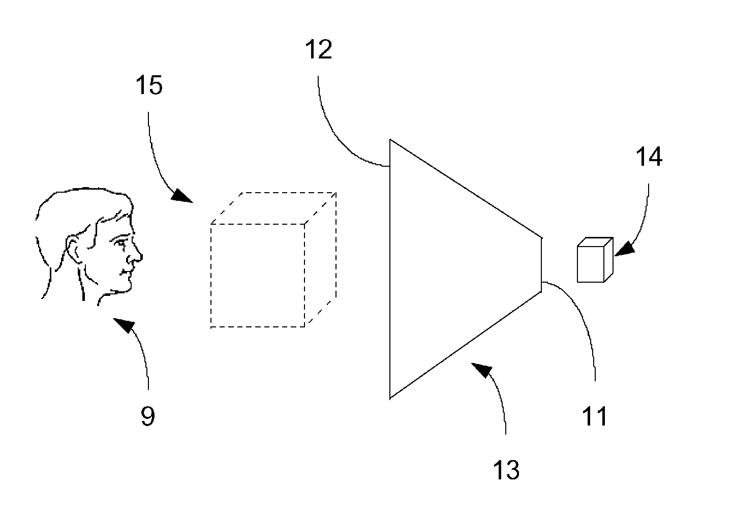
[0091]FIG. 4 shows how the Present Invention would be used to display a magnified image. In the figure, observer 9 sees magnified image 15 reconstructed from unmagnified object or scene 14. Observer 9 is closer to and looking at matrix lens array 12. Unmagnified object or scene 14 is positioned closer to matrix lens array 11. Magnifying or enlarging optics are contained within transmigrator 13 and are not shown in the figure.

[0092]The separation characteristic is either a vector or a two dimensional matrix. There are as many elements in each dimension of the matrix as there are elemental images in the integral frame. If the integral frame is uni-dimensional (i.e., comprised of a linear array of elemental images), then the matrix is a vector, and the number and arrangement of elements of the vector is the same as the number and arrangement of elemental images in the integral frame. The value of the leftmost element of that vector is twice the distance from the leftmost edge of the le...

second embodiment

[0103]An exemplary instance of the Present Invention is shown in FIG. 11(b). In the figure, the output planar face of a CRT 28 displaying an integral frame (or frames) is bonded to small face 3 (not shown in the figure) of transmigrator 13. The image of the integral frame from the CRT is magnified within transmigrator 13 and processed by matrix lens array 12 to produce a reconstructed three-dimensional image represented by the integral frame.

[0104]FIG. 11(c) shows one face of a liquid crystal display (LCD), 30, bonded to the surface of the small planar face of the device. Illumination of the LCD occurs externally on its non-bonded face by light rays 26. LCD 30 modulates the light rays by means known to those of ordinary skill, and produces a display of an integral frame. The integral frame is magnified within transmigrator 13 and processed by matrix lens array 12 to produce a reconstructed three-dimensional image represented by the integral frame.

[0105]FIG. 11(d) shows one face of L...


PUM


Abstract

A Modular Integral Magnifier that produces a uniformly magnified orthoscopic three-dimensional image of an original three-dimensional scene. The optical elements to achieve this effect are always maintained in relative alignment and registration regardless of movement and temperature deformations. The modules may be used together to construct a large composite high resolution viewing aperture or screen for large audiences to observe the magnified three-dimensional image. It may be used with photography, videography, or optical imaging of live scenes. It may be used for both still-life and animated three-dimensional images.

Description

CROSS REFERENCE TO RELATED APPLICATIONS[0001]This U.S. Non-Provisional patent application is a continuation-in-part of and claims the benefit of pending U.S. Non-Provisional application Ser. No. 10 / 292,137 (published as U.S. 2003-0160864 A1) filed on Nov. 12, 2002, entitled SYSTEM AND APPARATUS FOR RECORDING AND PROJECTING 3-DIMENSIONAL IMAGES (hereinafter the 137-Application); which in-turn is a continuation of and claims the benefit of U.S. Non-Provisional application Ser. No. 09 / 749,984 filed on Dec. 27, 2000 (having matured into U.S. Pat. No. 6,593,958 issued on Jul. 15, 2003—hereinafter the 958-Patent) entitled SYSTEM, APPARATUS AND METHOD FOR THE RECORDING AND PROJECTION OF IMAGES IN SUBSTANTIALLY 3-DIMENSIONAL FORMAT (hereinafter the 984-Application); which in-turn is a continuation of and claims the benefit of U.S. Non-Provisional application Ser. No. 09 / 111,990 (hereinafter the 990-Application) filed on Jul. 8, 1998 (having matured into U.S. Pat. No. 6,229,562 issued on May...

Claims


Application Information

Patent Timeline
Patent Type & Authority Patents(United States)
IPC IPC(8): G02B27/10G02B27/22G03H1/26H04N13/305H04N13/307
CPCG02B25/008H04N13/0497G02B27/2214G03H1/26H04N13/0406G02B27/027G02B3/005G02B3/0056G02B3/0062H04N13/307H04N13/398H04N13/305G02B30/27
Inventor KREMEN, STANLEY H.
Owner KREMEN STANLEY H
Why Eureka
Try Eureka