Counterfeit detection apparatus

a detection apparatus and anti-counterfeit technology, applied in the field of anti-counterfeit detection apparatus, can solve the problems of difficult to duplicate features, line printing patterns, and fine lines printed behind both the portrait and the u.s. treasury building, and achieve the effect of reducing the difficulty of counterfeiting

Inactive Publication Date: 2002-11-07
COHEN ROY
View PDF9 Cites 45 Cited by
  • Summary
  • Abstract
  • Description
  • Claims
  • Application Information

AI Technical Summary

Problems solved by technology

As such, the US Government and other monetary issuing agencies have added a number of very difficult to duplicate features to the paper currency.
8. Fine Line Printing Patterns--The fine lines printed behind both the portrait and the U.S. Treasury Building are difficult to replicate.
9. Microprinting--Because they're so small, microprinted words are hard to replicate.
There are means such as light tables, ultraviolet lamps, and illuminated magnifiers to individually or in some cases in combination to examine these features, but none provide an ability in a compact low cost device to examine a sufficient number to be certain of a bills validity.
As such the Mastnak invention cannot adequately magnify the microprinting for recognition as it is unidirectional in its magnification.
Secondly the method of illumination is also flawed as both the back and front illumination are caused by end illumination the lens and the diffuser.
Again, the efficacy in illuminating the currency in this manner without benefit of directive optics is likewise flawed.
Mastnak's substitution of an ultraviolet lamp for the broadband visual spectrum lamp is similarly but more so flawed.
Ultraviolet excited fluorescence visibility is very difficult to view in room light without having a shroud to limit the effects of ambient light.
UvB and uvc will accomplish fluorescence but are also more harmful and not suggested for this application.

Method used


Image

  • Counterfeit detection apparatus
  • Counterfeit detection apparatus
  • Counterfeit detection apparatus

Examples


Embodiment Construction

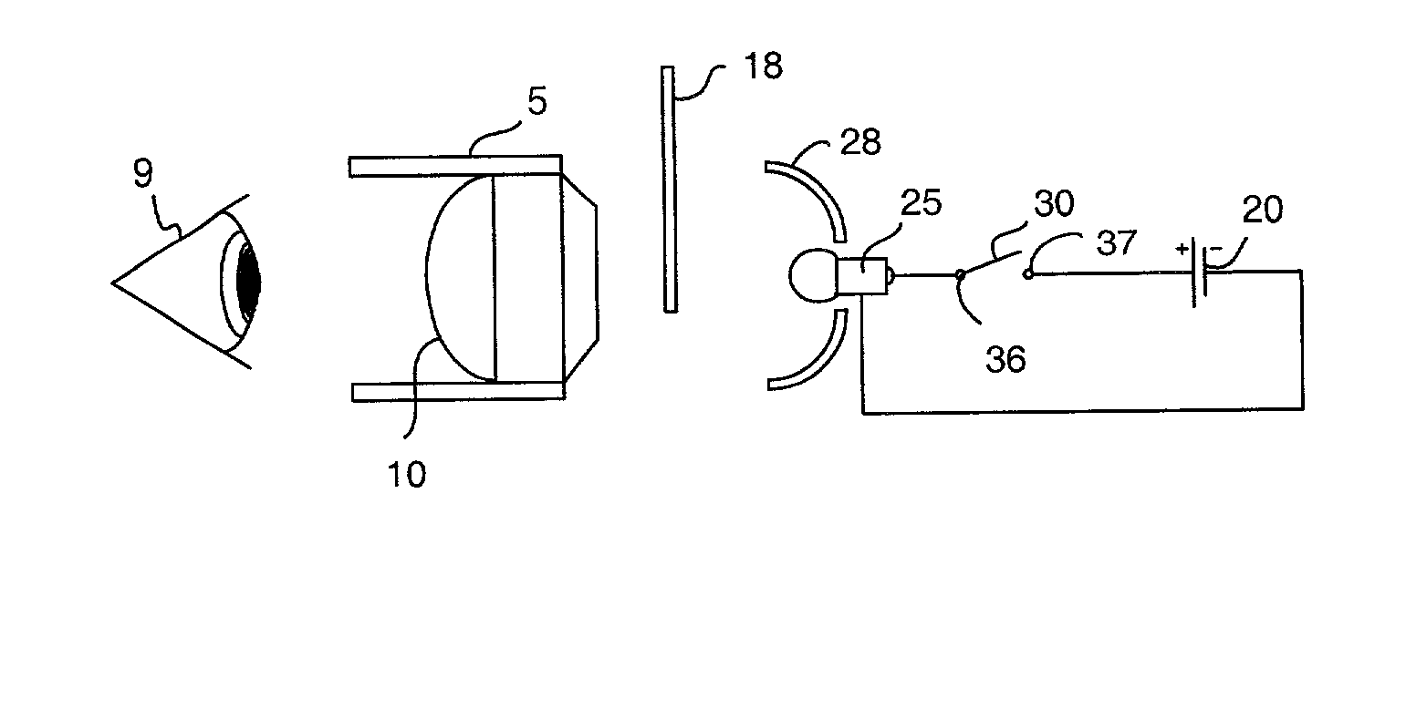
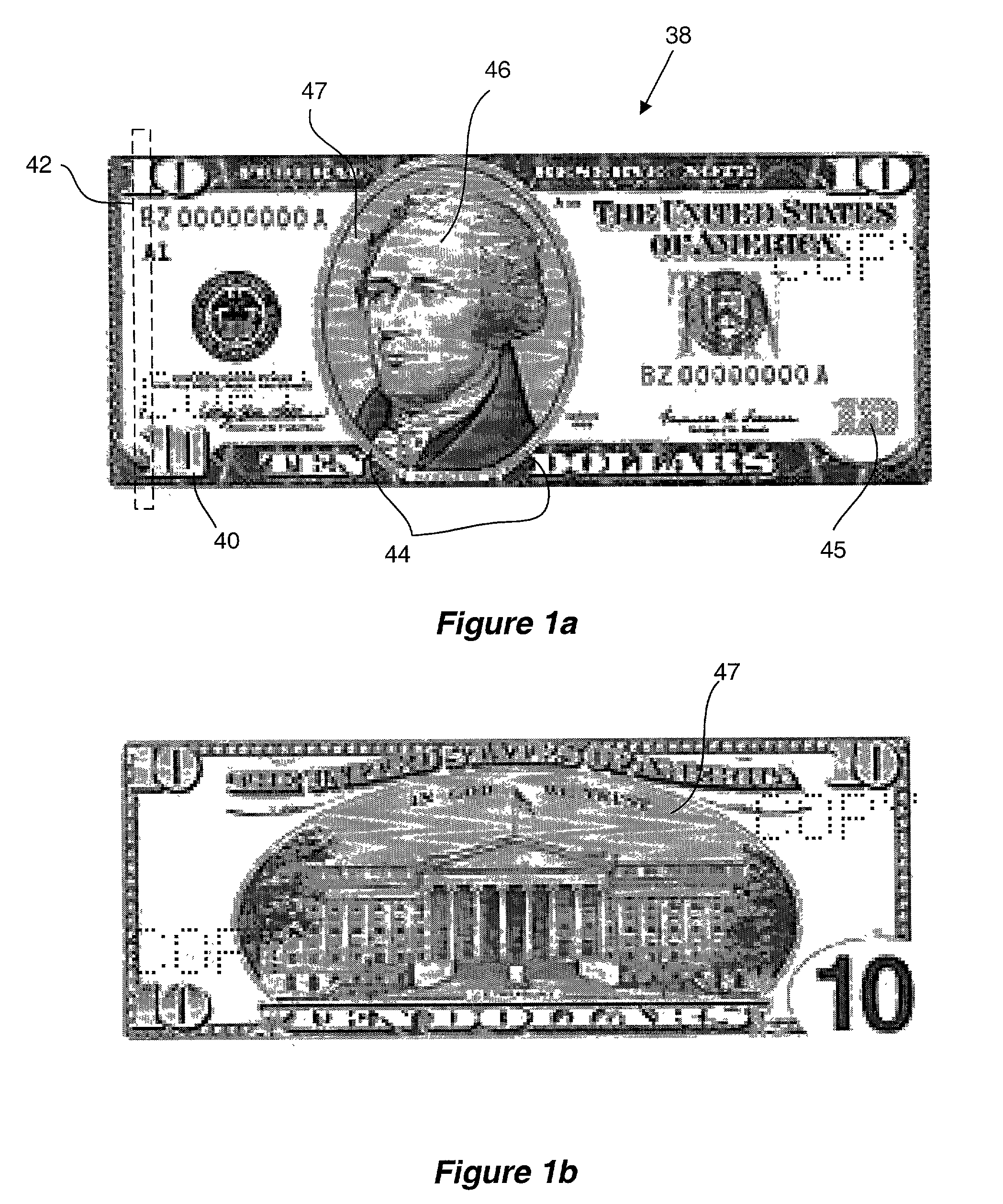
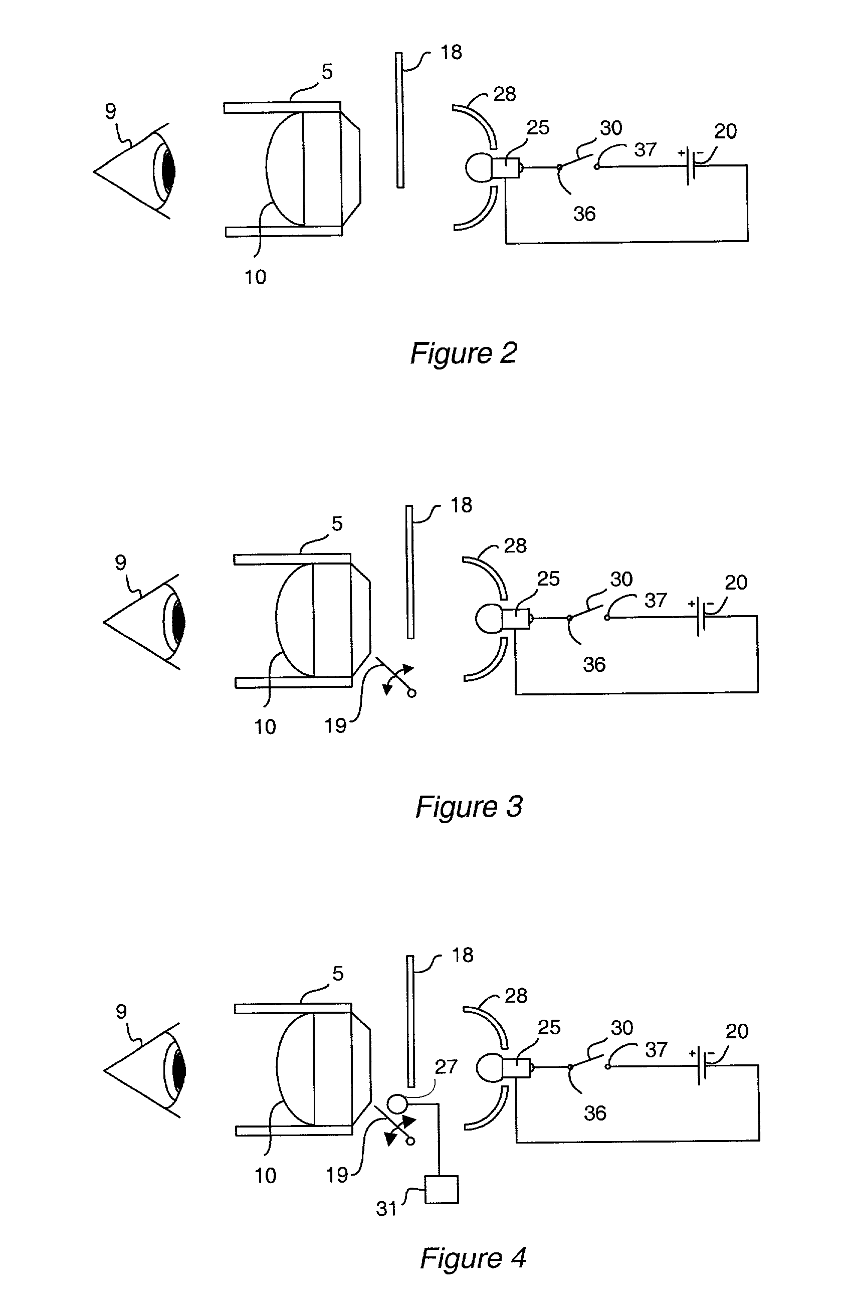
[0036] The illustrated FIGS. 1 through 8 are herein referenced to depict the various features of the present invention. FIG. 1a and 1b depicts a facsimile of the US $10 bill 38 as a reference to the zones of interest for validating the authenticity of a US $10 dollar bill. It will be recognized by those skilled in the art that other currency denominations of the United States as well as currency with security features of other nations can be validated in the same manner. It will also be recognized that other documents such as personal and corporate checks are presently utilizing microprinting, watermarks, and other security measures that the present invention will be useful to detect and view.

[0037] Item 40 has microprinting within the border of the numeral 10 and 44 microprinting around the lower rim of the portrait 46. Said microprinting is approximately 0.2 millimeters or 0.008 inches high. It will be recognized by those skilled in the art that magnification of this feature is es...


PUM


Abstract

A counterfeit detection device that is useful for optically examining the security features of currency to determine its authenticity. The apparatus places the currency at the object plane of a magnifying lens suitable for enlarging the image of the microprinting as well as examining other fine features of the bill. In one embodiment, the device consists of a rear illuminating light source a bill positioning slot a magnifying lens, and an environmental light shade. Further embodiments include a capability of front illumination to detect the color shifting ink, an ultraviolet light source causal to viewing the phosphorescent glow of the polyester thread with its identifying color. And finally, a version with a swing-away lens to view the watermark unmagnified.

Description

CROSS-REFERENCES TO RELATED APPLICATIONS[0001] Not Applicable[0002] Not applicableMICROFICHE APPENDIX[0003] Not Applicable[0004] 1. Field of the Invention[0005] The present invention relates to the detection of security features on monetary documents and the like. The US Federal Government has taken steps in recent years to combat counterfeiting of paper currency. Other monetary issuing agencies throughout the world have taken like steps. Additionally, banking organizations have added security features to other documents such as checks to impede forgery.[0006] 2. The Prior Art[0007] The advent of inexpensive computer and color printing and copying systems has made counterfeiting a much easier task than heretofore possible. As such, the US Government and other monetary issuing agencies have added a number of very difficult to duplicate features to the paper currency. The list below is particular to the US $10 bill but is indicative of the remainder of commonly circulated United State...

Claims


Application Information

Patent Timeline
Patent Type & Authority Applications(United States)
IPC IPC(8): G07D7/00G07D7/12
CPCG07D7/128
Inventor COHEN, ROY
Owner COHEN ROY
Why Eureka
Try Eureka