Tear tape applicator for ream wrap and other packaging materials

a technology of ream wrap and applicator, which is applied in the direction of packaging goods, paper/cardboard containers, box making operations, etc., can solve the problems of destroying the integrity of the wrapped structure, exposing and scattering the loose sheets of paper remaining in the ream, and affecting the integrity of the entire wrapped ream, so as to prevent physical damage and scatter loose parts.

a technology of ream wrap and applicator, which is applied in the direction of packaging goods, paper/cardboard containers, box making operations, etc., can solve the problems of destroying the integrity of the wrapped structure, exposing and scattering the loose sheets of paper remaining in the ream, and affecting the integrity of the entire wrapped ream, so as to prevent physical damage and scatter loose parts.

US20050202949A1Inactive Publication Date: 2005-09-15COATING EXCELLENCE INT

Image

  • Tear tape applicator for ream wrap and other packaging materials
  • Tear tape applicator for ream wrap and other packaging materials
  • Tear tape applicator for ream wrap and other packaging materials

Examples


Embodiment Construction

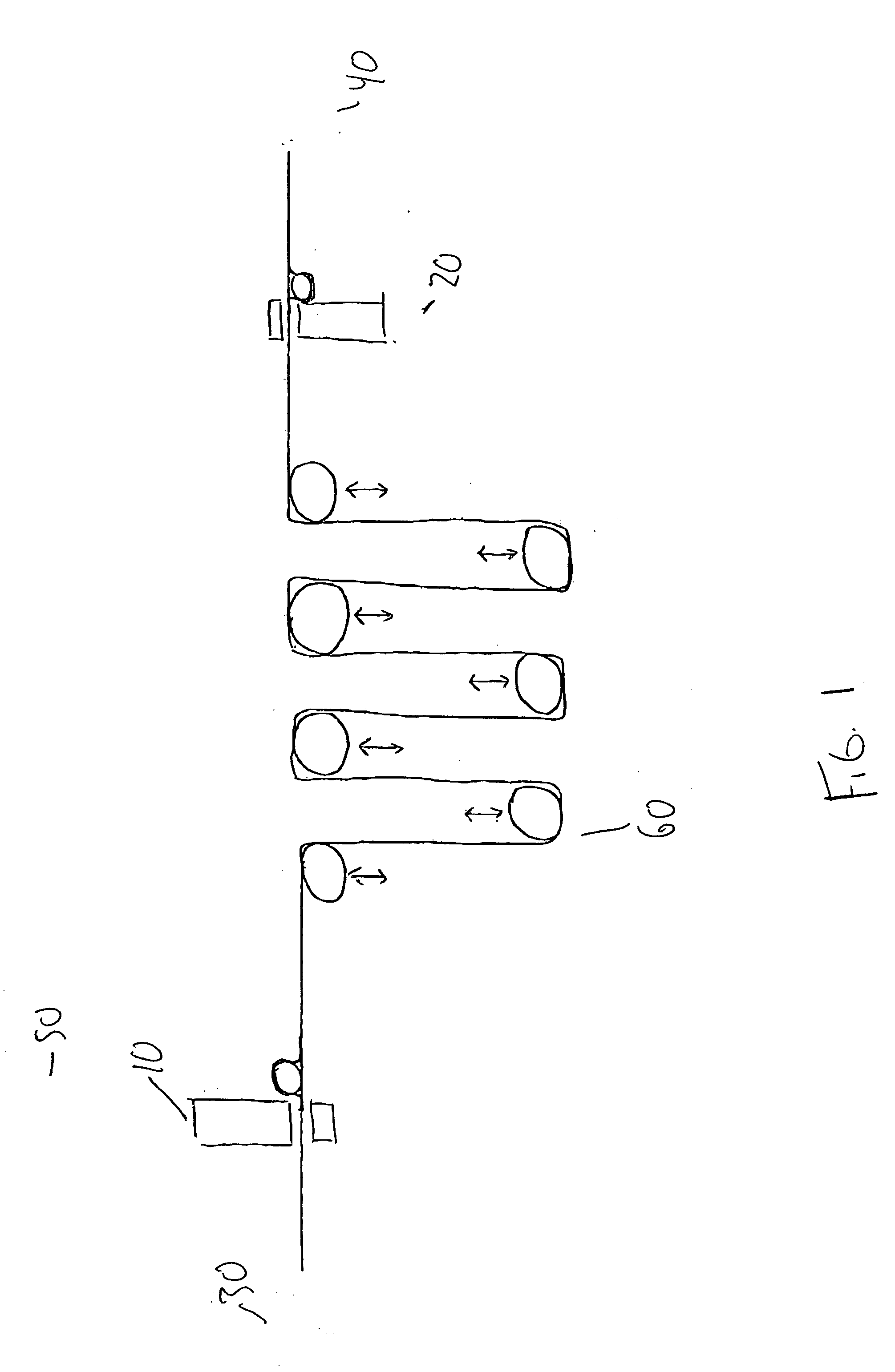
[0036] In one embodiment of the present invention, shown in FIG. 1, a tear tape applicator unit 10 and 20 is attached to either the wind-up 30 or unwind end 40 of a rewinding line 50. The applicator comprises, in part, a number of festoon or dancer rolls 60 that move up and down, pulling the web of ream wrap or other packaging material and momentarily stopping it while the wind-up and unwind roll speeds remain constant. When the web is momentarily stopped, the applicator then cuts and applies a strip of tear tape at 1 to 10 places across the web of the ream wrap or other packaging material.

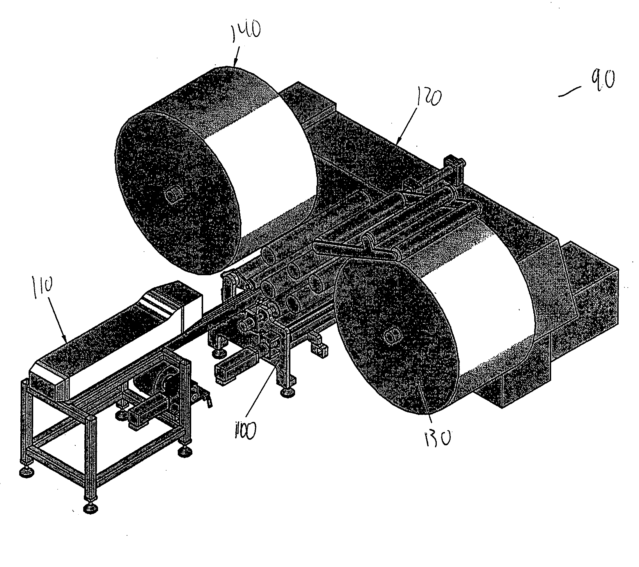
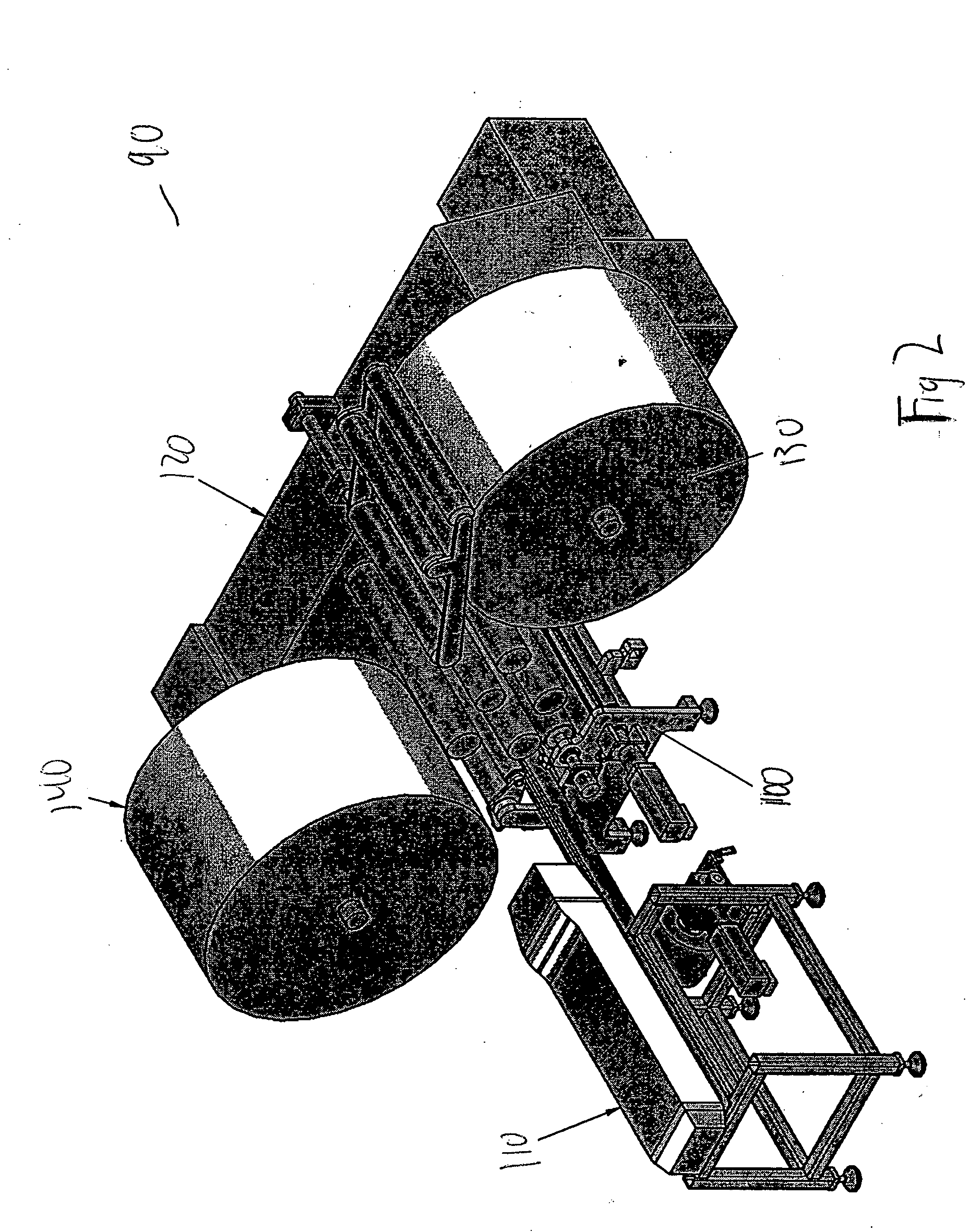
[0037]FIG. 2 shows a system 90 for applying tear tape comprising a tear tape applicator assembly 100, a laser / tear tape unwind assembly 110, Stanford winder 120, a rewind roll 130 and an unwind roll 140.

[0038]FIG. 3 illustrates a system 200 which comprises a laser 202 with a laser beam 204 and a beam focal length 206. The system further comprises a tear tape roll 208, rider roll 210, tear tape r...


PUM

PropertyMeasurementUnit
speedsaaaaaaaaaa
widthaaaaaaaaaa
pressureaaaaaaaaaa

Abstract

Equipment for applying tear tape to ream wrap, packaging material, and / or other paper or film products. The equipment is attached to rewinding and / or packaging equipment.

Description

RELATED PATENT APPLICATIONS [0001] The present application is a continuation in part of U.S. patent application Ser. No. 10 / 797,312.FIELD OF THE INVENTION [0002] The present invention relates to equipment for applying tear tape to ream wrap and / or other paper or film products or packaging materials. The invention relates to equipment that is attached to rewinding and / or packaging equipment. BACKGROUND OF THE INVENTION [0003] Wrapper for reams (i.e., 500 sheets) of cut paper is typically manufactured in large rolls, printed or not printed, and rewound and / or cut to specific sizes. The wrapper is then sold to paper manufacturers who package the reams of paper on wrapping lines. Reams of cut paper (8½×11, etc.) for copy machines, computers, printers, and other home and office applications are most commonly packaged for shipping, storage and retail sale in ream wrap made of various materials, including paper, paper / film combinations, and solid plastic films. As more people have acquired...

Claims


Application Information

Patent Timeline
15 Sep 2005
Publication
US20050202949A1
IPC
B31B1/90; B65D1/00; B65D65/26; B65D85/12
CPC
B65B25/14; B65B41/16; B65B61/182; B65D75/66; B31B50/8127; Y10T428/1334; Y10T225/12
Inventors
NOWAK, MICHAEL; SCHNEIDER, DAVID