
Optical termination pedestal

a technology of optical fiber connection and pedestal, which is applied in the field of pedestals, can solve the problems of difficult to identify the optical fiber of the distribution cable to be interconnected with the optical fiber of a particular drop cable, the process of configuring the mid-span access location is not only time-consuming, but often must be accomplished by a highly skilled field technician at significant cost and under field working conditions, and the difficulty of reconfiguring the optical fiber connection in the splice closure is particularly difficul

Inactive Publication Date: 2005-09-22
CORNING OPTICAL COMM LLC
View PDF99 Cites 115 Cited by
  • Summary
  • Abstract
  • Description
  • Claims
  • Application Information

AI Technical Summary

Benefits of technology

[0007] To achieve the foregoing and other objects, and in accordance with the purpose of the present invention as embodied and broadly described herein, the present invention provides various embodiments of an optical termination pedestal including a housing configured as a “canister” or “butt” type closure that may be mounted onto a conventional pedestal base or onto a base incorporated into a below-grade vault or hand hole. A plate disposed within the housing is provided with a seal between the housing and the periphery of the plate. The plate may serve as a bulkhead with one or more connector ports mounted on the plate for receiving a connectorized optical fiber of a distribution cable on one side of the connector port and a pre-connectorized fiber optic drop cable on the other side of the connector port. The plate also has one or more cable entrance and exit ports for routing the distribution cable and any fiber optic drop cables utilized in forming optical connections, for example, by fusion splicing or by interconnecting pigtails through a connector adapter sleeve. The plate separates the interior cavity of the optical termination pedestal into a first compartment for managing terminated optical fibers and optical connections and a second compartment for receiving the distribution cable and the drop cables. Advantageously, the plate substantially seals the first compartment relative to the second compartment and thereby prevents moisture from entering the first compartment, for example in the event of a flood condition. An optical termination pedestal according to the present invention permits a field technician to establish desired optical connections in a fiber optic communications network and to reconfigure optical connections after initial installation of the pedestal at a convenient mid-span access location along the length of a feeder cable, a distribution cable or a branch cable of a fiber optic network.

Problems solved by technology

In particular, it is often difficult to identify an optical fiber of the distribution cable to be interconnected with an optical fiber of a particular drop cable.
In either case, the process of configuring the mid-span access location is not only time consuming, but frequently must be accomplished by a highly skilled field technician at significant cost and under field working conditions that are less than ideal.
In networks in which a mid-span access location is enclosed within a splice closure, reconfiguring the optical fiber connections in the splice closure is especially difficult, based in part on the inaccessible location of the closure and the inability to readily remove the closure from the distribution cable.
Further, once the optical connections are made, it is often labor intensive, and therefore costly, to reconfigure the existing optical connections or to add additional optical connections.

Method used


Image

  • Optical termination pedestal
  • Optical termination pedestal
  • Optical termination pedestal

Examples


Embodiment Construction

[0020] The present invention will now be described more fully hereinafter with reference to the accompanying drawings in which exemplary embodiments of the invention are shown. This invention may, however, be embodied in many different forms and should not be construed as limited to the embodiments set forth herein. These exemplary embodiments are shown and described so that this disclosure will be both thorough and complete, and will fully convey the scope of the invention to those skilled in the art. Like reference numbers refer to like elements throughout the various drawings.

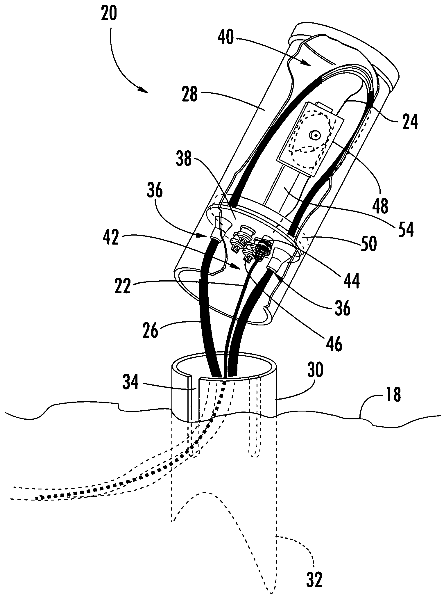
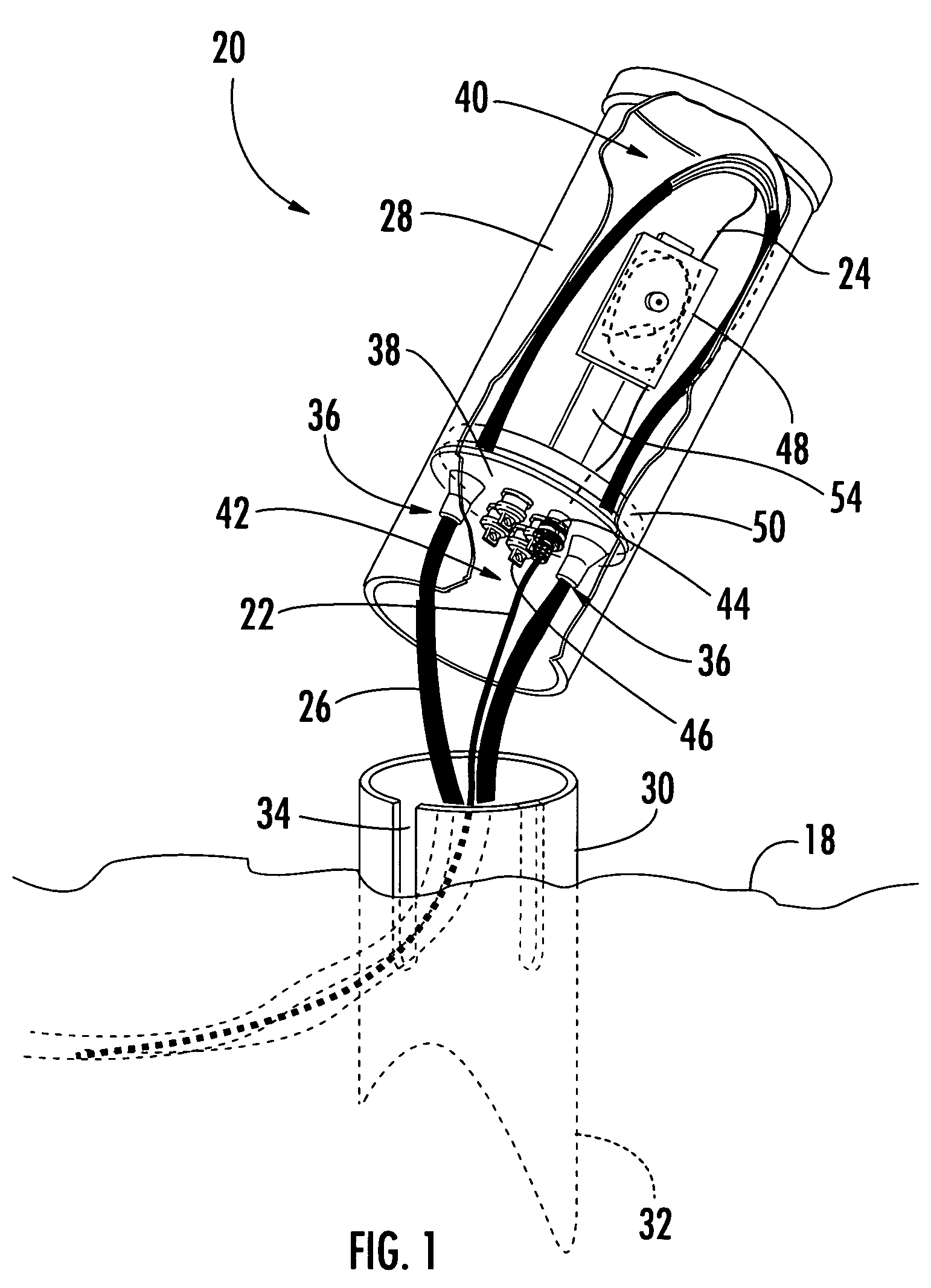
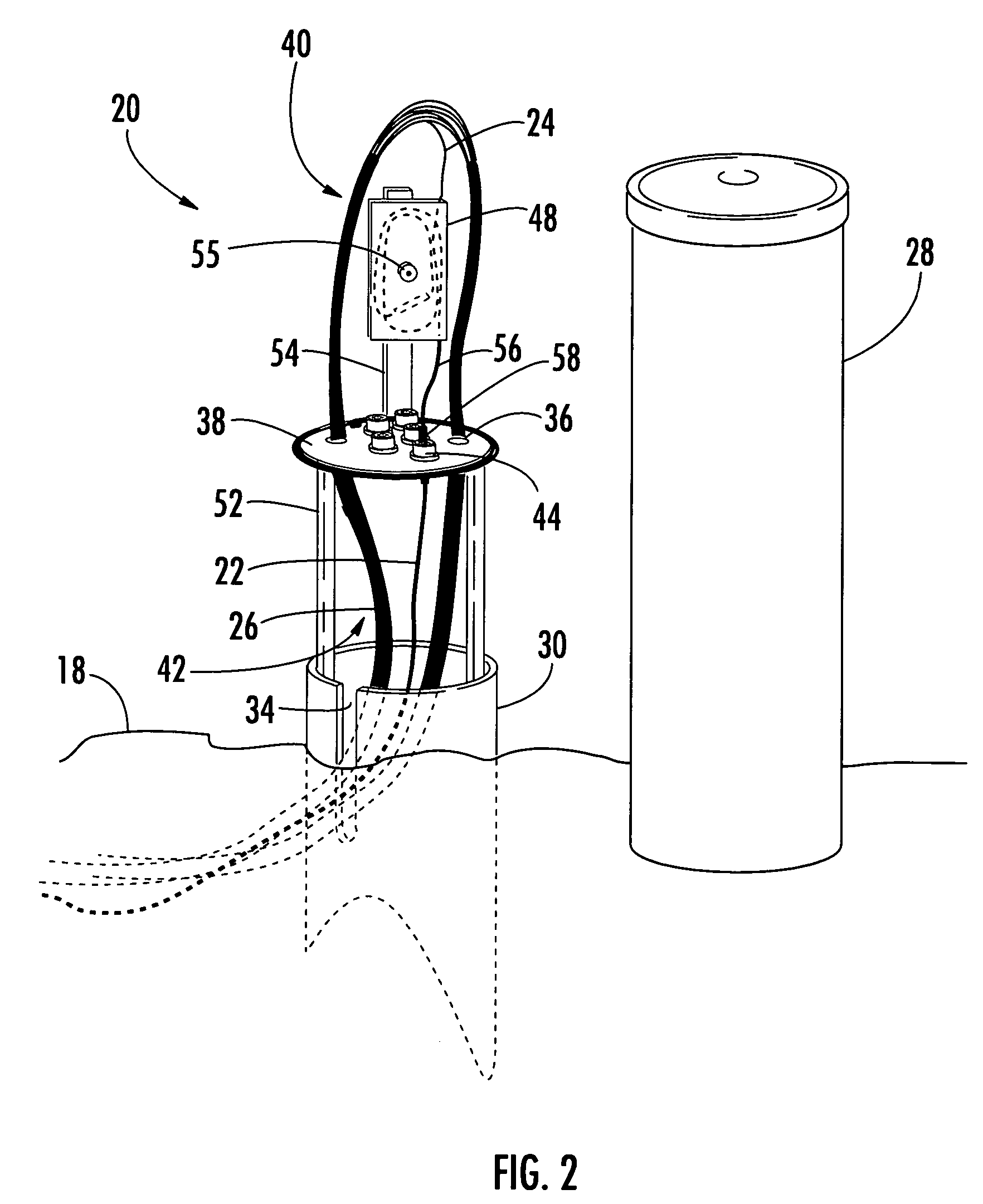
[0021] The present invention provides various embodiments of an optical termination pedestal defining an interior cavity adapted for housing fiber optic cables, terminated optical fibers and optical connections, and for sealing the terminated optical fibers and optical connections against adverse environmental conditions, such as dust, dirt, infestation and moisture, and in particular, a flood condition. Th...


PUM


Abstract

An optical termination pedestal defines an interior cavity for interconnecting an optical fiber of a distribution cable and an optical fiber of a drop cable. The pedestal includes a base, a housing positioned over the base, and a plate secured to the housing or the base. The plate separates the interior cavity into a first compartment and a second compartment and has at least one cable port for routing the distribution cable into the first compartment. At least one connector port may be provided on the plate for receiving a connectorized optical fiber of the distribution cable from the first compartment and a pre-connectorized drop cable from the second compartment. The plate is provided with an O-ring to seal the first compartment relative to the second compartment. As a result, a sealed splice closure is created within the interior cavity without the need for a separate enclosure.

Description

BACKGROUND OF THE INVENTION [0001] 1. Field of the Invention [0002] The present invention relates generally to a pedestal adapted for use in a fiber optic communications network, and more specifically, to an optical termination pedestal adapted for interconnecting an optical fiber of a distribution cable and an optical fiber of a fiber optic drop cable within an interior cavity defined by the pedestal. [0003] 2. Description of the Related Art [0004] Optical fiber is increasingly being used for a variety of broadband applications including voice, video and data transmissions. As a result of the ever-increasing demand for broadband communications, fiber optic networks typically include a large number of mid-span access locations at which one or more optical fibers are branched from a distribution cable. These mid-span access locations provide a branch point from the distribution cable leading to an end user, commonly referred to as a subscriber, and thus, may be used to extend an “all...

Claims


Application Information

Patent Timeline
IPC IPC(8): G02B6/38G02B6/44
CPCG02B6/3897G02B6/4451G02B6/4444G02B6/501G02B6/44528
Inventor VO, CHANH C.BRADLEY, JOHN J.BURNS, SCOTT C.CASTONGUAY, GUYCLAPP, DONNIE R. JR.COX, TERRY D.HIGA, LIEM H.SIMS, STEVEN R.STABER, HARLEY J.STRAUSE, KEVIN L.
Owner CORNING OPTICAL COMM LLC
Features
  • Generate Ideas
  • Intellectual Property
  • Life Sciences
  • Materials
  • Tech Scout
  • Unparalleled Data Quality
  • Higher Quality Content
  • 60% Fewer Hallucinations
Learn More