Method and apparatus for detecting signals, and transmitting apparatus and receiving apparatus using the same

Inactive Publication Date: 2005-09-29
SANYO ELECTRIC CO LTD
View PDF12 Cites 5 Cited by
  • Summary
  • Abstract
  • Description
  • Claims
  • Application Information

AI Technical Summary

Benefits of technology

[0010] By implementing the above apparatus, automatic gain control is performed before detecting signals, so that the correlation values can be accurately derived without increasing the distortion

Problems solved by technology

However, there is a possibility that the maximum value of correlation values cannot be accurately detected in the multi-path fading environment or in the environment of low SNR (Signal to Noise Ratio).
That is, there are cases where the maximum value of correlation values cannot be detected at the proper detection timing and the maximum value

Method used


Image

  • Method and apparatus for detecting signals, and transmitting apparatus and receiving apparatus using the same
  • Method and apparatus for detecting signals, and transmitting apparatus and receiving apparatus using the same
  • Method and apparatus for detecting signals, and transmitting apparatus and receiving apparatus using the same

Examples


first embodiment

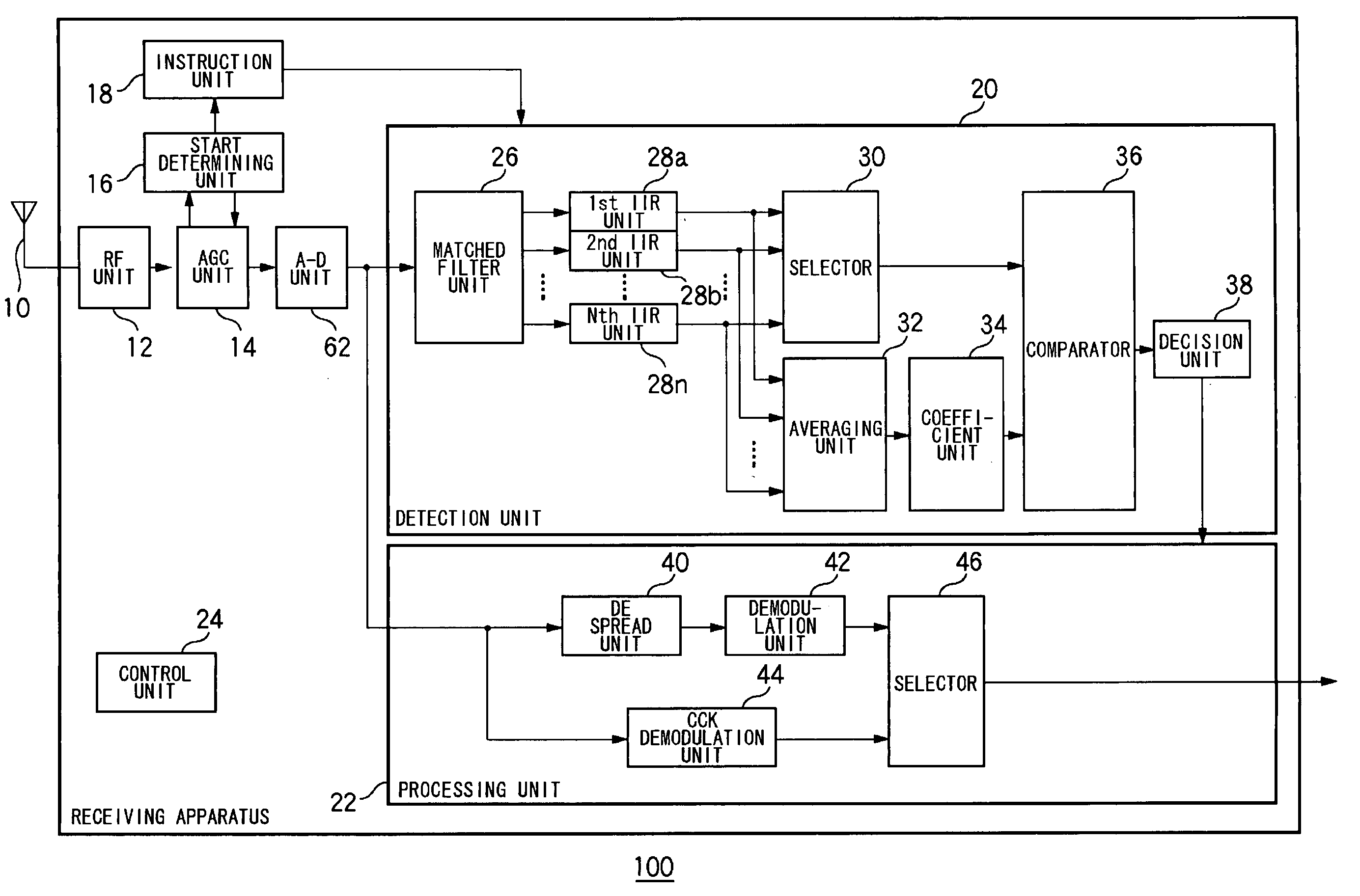
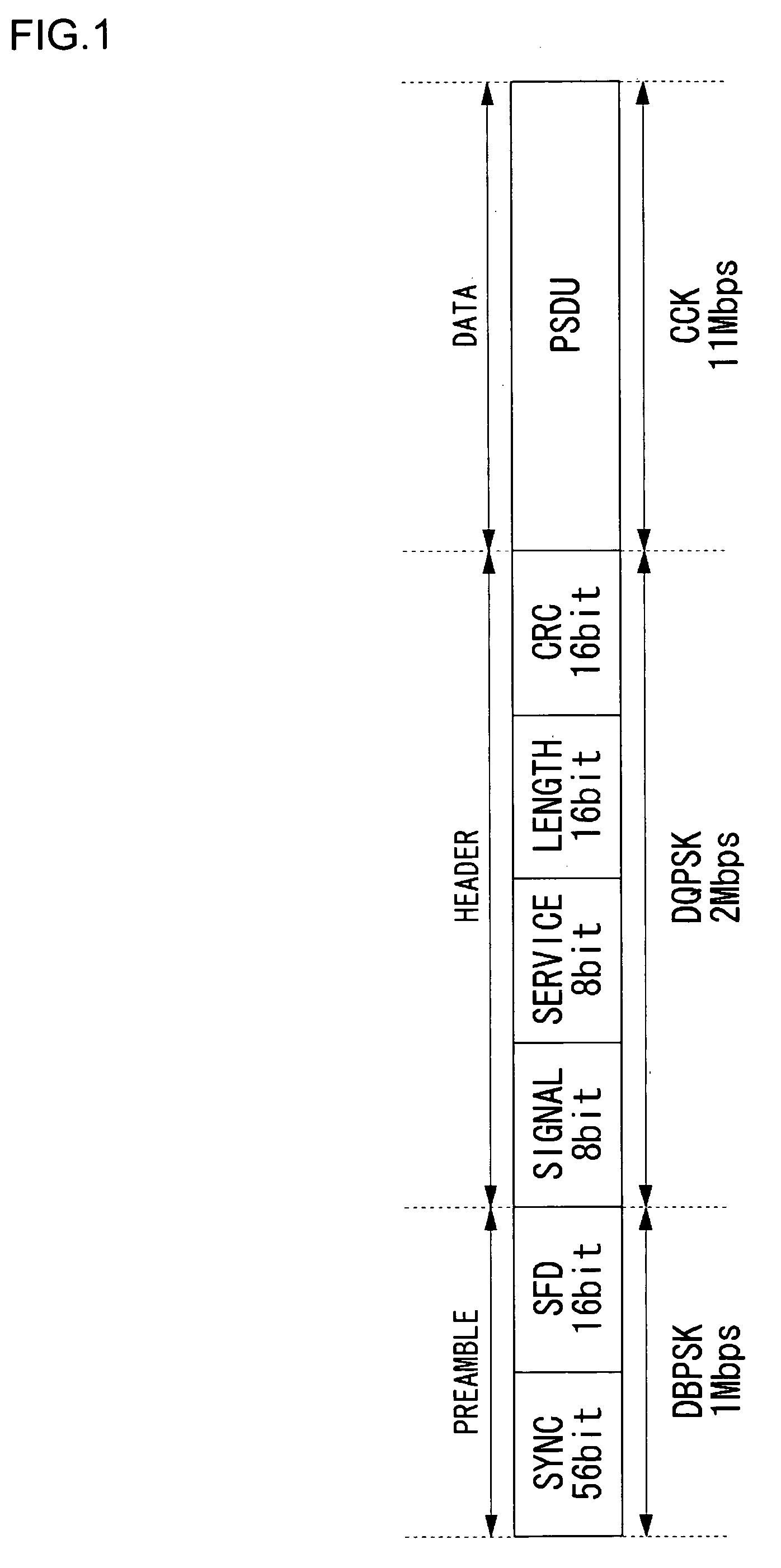
[0029] Before describing the present invention in a specific manner, an outline of the present invention will be described first. A first embodiment according to the present invention relates to a receiving apparatus of wireless LAN that conforms to the IEEE802.11b standard. The receiving apparatus receives signals transmitted from a transmitting apparatus via the wireless transmission path. As described earlier, the characteristics of wireless transmission path is such that it fluctuates greatly. That is, there may be a case where the strength of a desired signal is small and therefore the strength of noise is relatively large and there may be another case where the strength of a desired signal is large and therefore the strength of noise is relatively small. Generally, the former case makes it difficult for the signals to transmit smoothly. A receiving apparatus according to the present embodiment performs a correlation processing on a signal which has been subjected to spectrum-s...

second embodiment

[0062] A second embodiment according to the present invention relates to a transmitting apparatus of wireless LAN compliant with IEEE802.11b standard. CSMA is used in the wireless LAN of IEEE802.11b standard. And in CSMA the transmitting apparatus performs carrier sense before transmitting signals, and then transmits the signals if no signal is detected. A transmitting apparatus according to the second embodiment uses the signal detection technique described in the first embodiment for the carrier sense.

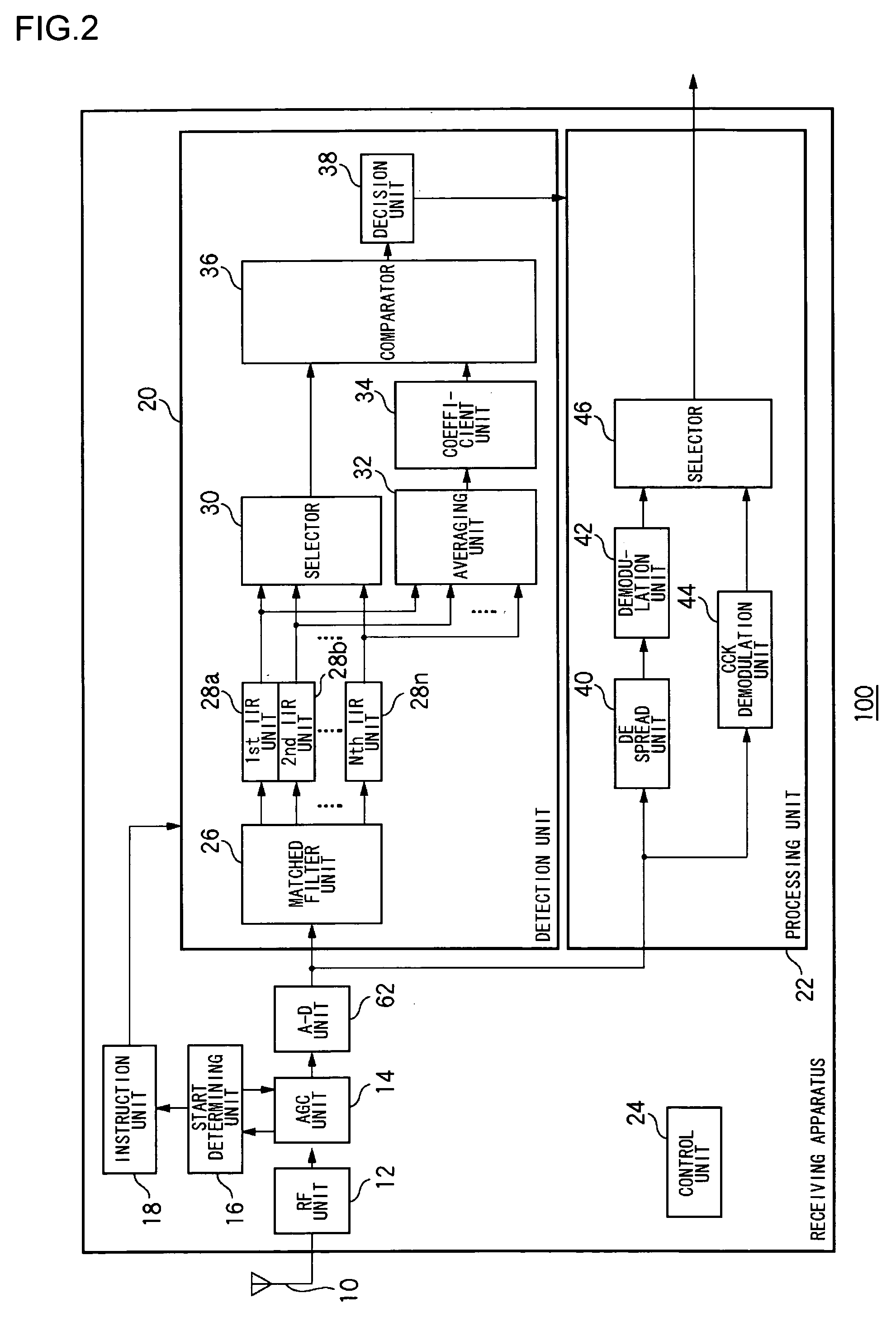
[0063]FIG. 11 illustrates a structure of a communication apparatus 110 according to the second embodiment of the present invention. The communication apparatus 110 includes an RF unit 12, an AGC unit 14, an A-D unit 62, a start determining unit 16, an instruction unit 18, a detection unit 20, a transmitter 60 and a control unit 24. The detection unit 20 includes a matched filter unit 26, a first IIR unit 28a and a second IIR unit 28b, which are generically referred to as IIR units 2...


PUM


Abstract

A start determining unit measures the strength of a signal which has been frequency-converted by an radiofrequency unit, and decides the start of a signal detection processing if the measured strength of a signal becomes greater than a predetermined threshold value. When the start of a signal detection processing is notified, an automatic gain control unit amplifies the signal which has been frequency-converted by the radiofrequency unit. A matched filter unit generates a correlation value for each sampling timing from signals outputted from an analog-to-digital unit. An infinite impulse response unit performs a statistical processing on the correlation values outputted from the matched filter unit, over a plurality of symbols. An averaging unit averages the correlation values on which the statistical processing has been performed. A coefficient unit multiplies the averaged correlation value by a coefficient. A decision unit determines that a signal to be received has been detected if, as a result of comparison by a comparison unit, the maximum value from a selector is large.

Description

BACKGROUND OF THE INVENTION [0001] 1. Field of the Invention [0002] The present invention generally relates to the signal detecting techniques, and it particularly relates to method and apparatus for detecting if the received signals contain a predetermined signal, and transmitting apparatus and receiving apparatus utilizing the same. [0003] 2. Description of the Related Art [0004] As a spread spectrum communication system using the radio frequency of 2.4 GHz band, the wireless LAN (Local Area Network) of IEEE802.11b standard has been developed and put to practical use. This wireless LAN realizes the maximum transmission rate of 11 Mbps by CCK (Complementary Code Keying) modulation. The signals, such as preambles or headers, which contain control signals therein are produced by spreading DBPSK- or DQPSK-modulated signals with spread codes. Here, DBPSK stands for Differential Binary Phase Shift Keying and DQPSK Differential Quadrature Phase Shift Keying. A receiving apparatus in the ...

Claims


Application Information

Patent Timeline
IPC IPC(8): H04B1/7073H04L25/02H04B1/707H04L27/06
CPCH04B1/7075H04B1/7093H04B1/70757
Inventor NISHIMURA, NAOAKIOKITA, TOMOKAZU
Owner SANYO ELECTRIC CO LTD
Why Eureka
Try Eureka