
Imaging apparatus with AF optical zoom

a technology of optical zoom and imaging apparatus, applied in the direction of printers, instruments, cameras, etc., can solve the problems of increasing the quantity of operation processing, unable to apply, and no longer being able to acquire a stable af detection value, so as to achieve the effect of correct derive the focus position and simple processing

Inactive Publication Date: 2010-12-07
SOCIONEXT INC
View PDF15 Cites 6 Cited by
  • Summary
  • Abstract
  • Description
  • Claims
  • Application Information

AI Technical Summary

Benefits of technology

The present invention is about a new imaging apparatus that can easily and securely correct focus state using an AF detection value. The invention solves problems that occurred when using the conventional methods of correcting focus state by reducing the influence of luminance value. The invention uses the rate of change in luminance value to correct the shift caused by the optical zoom and calculates the corrected AF detection value by multiplying the AF detection value by the inverse of the rate of change in luminance value. This evaluation value is used to accurately determine the focus position, even when the detection value includes other factors. The invention can be applied to both inexpensive and high-end cameras and is simple and easy to use.

Problems solved by technology

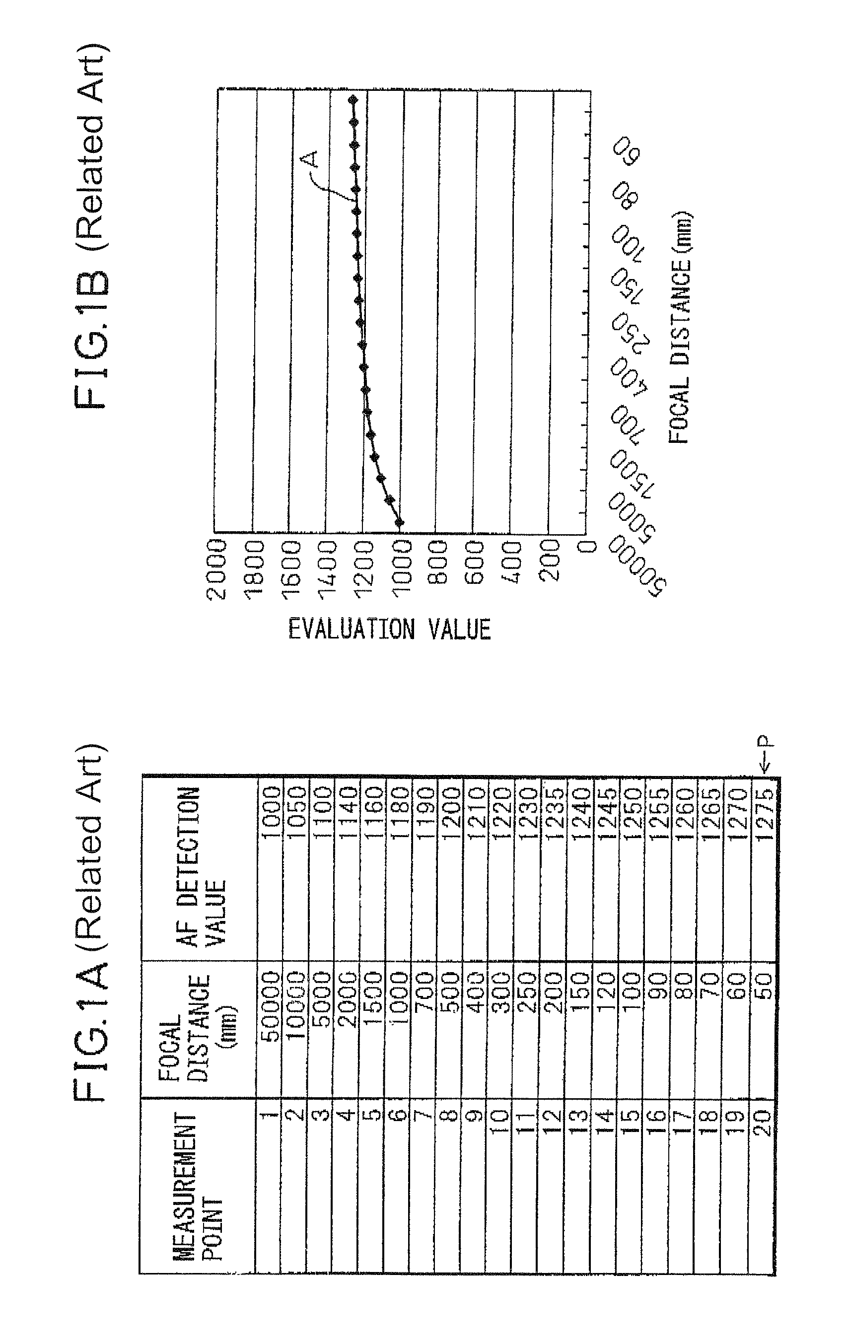
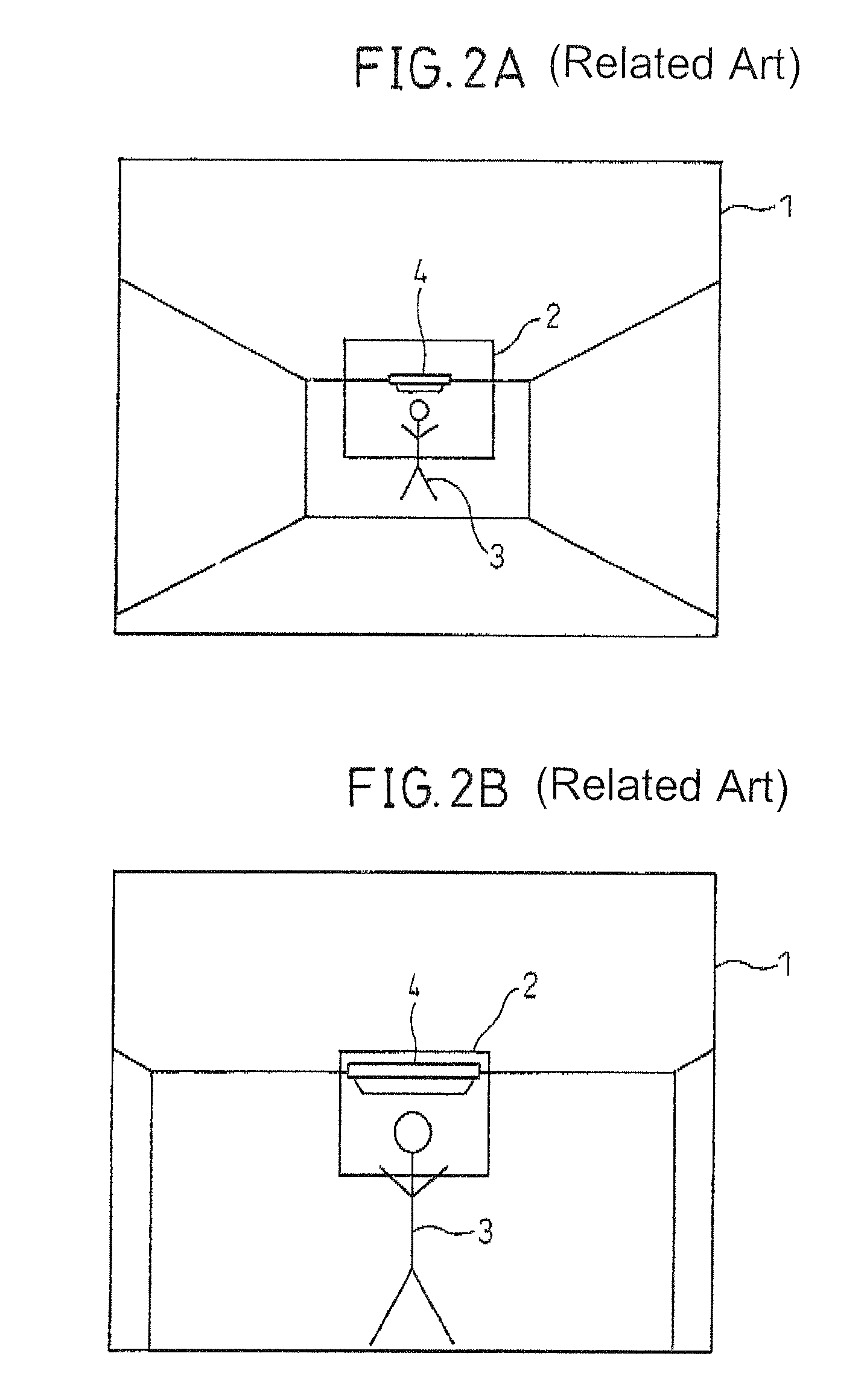
However, the configuration described in Japanese Unexamined Patent Publication (Kokai) No. 8-15601 handles AE-controlled imaging signal data as an object and as described in patent document 2, there is a problem that if auto-focus processing is performed while the AE control is performed, the quantity of operation processing is increased or a problem that it is no longer possible to acquire a stable AF detection value because the brightness of the subject changes when AF is started on the way of the AE convergence, and therefore, in general, the AE processing is not performed when the auto-focus processing is performed, and particularly in the case of an inexpensive camera, such as one attached to a mobile phone, the processing described in Japanese Unexamined Patent Publication (Kokai) No. 8-15601 cannot be applied.
Further, with the configuration described in Japanese Unexamined Patent Publication (Kokai) No. 2005-338514, there is a problem in that the variation of the calculated difference value does not necessarily specify proper correction.

Method used


Image

  • Imaging apparatus with AF optical zoom
  • Imaging apparatus with AF optical zoom
  • Imaging apparatus with AF optical zoom

Examples


Embodiment Construction

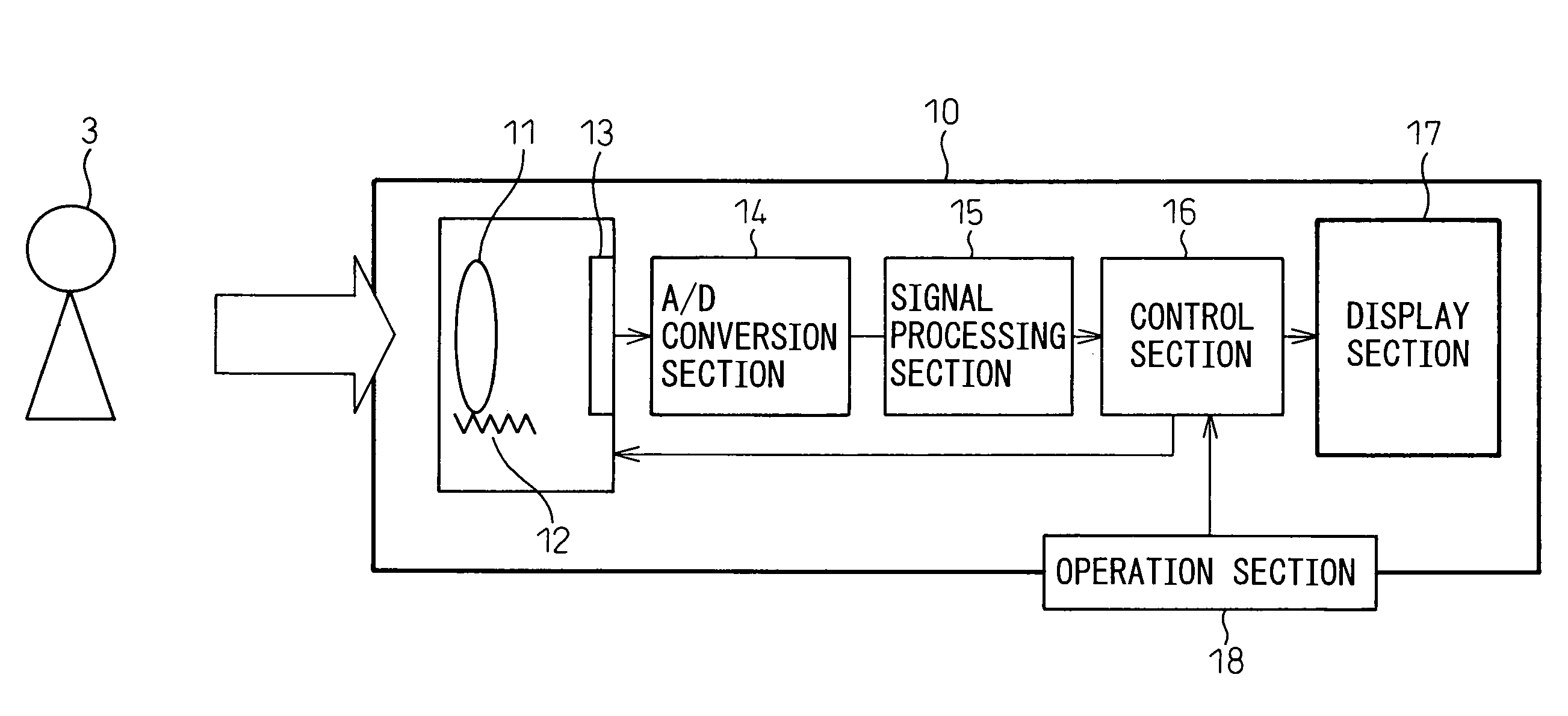
[0032]FIG. 3 is diagram showing a configuration of an auto-focus (AF) camera 10 in a first embodiment of the present invention. As shown in FIG. 3, the AF camera 10 comprises a lens section 11, an auto-focus drive section 12 for varying the focal distance to a subject by moving the lens of the lens section 11, a sensor section 13 for converting an image projected by the lens section 11 into an electric signal, an A / D conversion section 14 for analog-to-digital (A / D)-converting the electric signal from the sensor section 13, a signal processing section 15 for processing the digital imaging data from the A / D conversion section 14, a control section 16 for controlling each section, a display section 17 for displaying an imaged image, and a user interface of activation / termination of a camera, start / stop of auto-focus, start of photographing, etc., and also having an operation section 18 for delivering the control signal to the control section.

[0033]The auto-focus drive section 12 is ca...


PUM


Abstract

A novel imaging apparatus capable of correcting a focus state by an AF detection value both simply and surely has been disclosed. The imaging apparatus comprises an auto-focus drive section for moving a lens, an AF processing section for calculating an AF detection value indicating the focus state from imaging data, a luminance processing section for calculating a luminance value from the imaging data, a correction section for calculating a corrected AF detection value by correcting the calculated AF detection value by the calculated luminance value, and a control section for controlling the auto-focus drive section based on the calculated corrected AF detection value. The imaging data is data not having been subjected to auto-exposure processing.

Description

CROSS REFERENCE TO RELATED APPLICATION[0001]This application is based upon and claims the benefit of priority from the prior Japanese Patent Application No. 2006-262533, filed on Sep. 27, 2006, the entire contents of which are incorporated herein by reference.BACKGROUND OF THE INVENTION[0002]The present invention relates to a digital imaging apparatus, having an auto-focus function, including a digital camera and a camera attached to a mobile phone and, more particularly, to a technique to improve the focus position accuracy of a digital imaging apparatus.[0003]In a digital camera, the equipping of an auto-focus function for automatically focusing the camera has become widespread due to the increase in the number of pixels and an advance in functionality. The present invention is an invention of an auto-focus technique for judging a focus position by a detection value at each measurement point by shifting the focal point by moving the position of a lens.[0004]In general, the focus s...

Claims


Application Information

Patent Timeline
Patent Type & Authority Patents(United States)
IPC IPC(8): H04N5/232
CPCG03B3/00H04N5/23212G02B7/102H04N23/673H04N23/676G03B13/36G03B3/10H04N23/67H04N23/70
Inventor OKAWA, AKIRAYONEKAWA, TAKAAKIUENISHI, NORIYUKI
Owner SOCIONEXT INC
Learn More