MRI method for correcting amplitude of resonance signals

a magnetic resonance signal and amplitude correction technology, applied in the field of magnetic resonance imaging method, can solve the problem that quantitative information cannot be accurately extracted from magnetic resonance signals, and achieve the effect of accurate diffusion, perfusion and/or flow measurement, and accurate extraction of quantitative information

Inactive Publication Date: 2005-05-24
KONINKLIJKE PHILIPS ELECTRONICS NV
View PDF24 Cites 4 Cited by
  • Summary
  • Abstract
  • Description
  • Claims
  • Application Information

AI Technical Summary

Benefits of technology

[0006]It is an object of the invention to provide a magnetic resonance imaging method which enables accurate extraction of quantitative information from the magnetic resonance signals despite non-linearities i...

Problems solved by technology

Even though the distortions in the magnetic resonance image are accurately corrected by means of the known magnetic resonanc...

Method used


Image

  • MRI method for correcting amplitude of resonance signals
  • MRI method for correcting amplitude of resonance signals
  • MRI method for correcting amplitude of resonance signals

Examples


Embodiment Construction

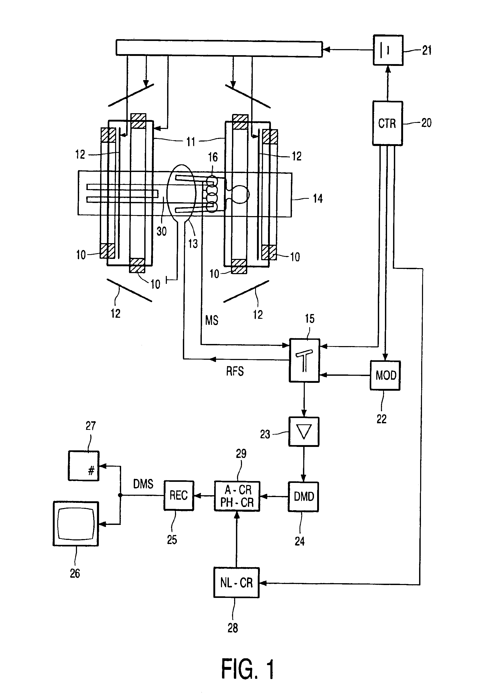
[0017]FIG. 1 shows diagrammatically a magnetic resonance imaging system in which the invention is used. The magnetic resonance imaging system includes a system of main coils 10 whereby the steady, uniform magnetic field is generated. The main coils are constructed, for example, in such a manner that they enclose a tunnel-shaped examination zone. The patient to be examined is introduced into said tunnel-shaped examination zone. The magnetic resonance imaging system also includes a number of gradient coils 11, 12 whereby magnetic fields with spatial variations, notably in the form of temporary gradients in separate directions, are superposed on the uniform magnetic field. The gradient coils 11, 12 are connected to a variable power supply unit 21. The gradient coils 11, 12 are energized by applying a current thereto by means of the power supply unit 21. The strength, the direction and the duration of the gradients are controlled by control of the power supply unit. The magnetic resonan...


PUM


Abstract

In a magnetic resonance imaging method flow quantities and diffusion quantities are measured in the presence of temporary magnetic gradient fields (gradient pulses). Signal amplitudes of the magnetic resonance signals and/or flow and diffusion quantities calculated from the magnetic resonance signals are corrected for non-linearities in the magnetic gradient fields.

Description

BACKGROUND OF THE INVENTION[0001]1. Field of the Invention[0002]The invention relates to a magnetic resonance imaging method wherein magnetic resonance signals are generated and temporary magnetic gradient fields are used.[0003]A magnetic resonance imaging method of this kind is known from U.S. patent specification U.S. Pat. No. 5,498,963.[0004]2. Description of the Prior Art[0005]The known magnetic resonance imaging method takes into account nonlinearities in the temporary magnetic gradient fields. The cited U.S. patent specification states that non-linearities in the temporary magnetic gradient fields give rise to distortions in the magnetic resonance image that is reconstructed from the magnetic resonance signals. In order to counteract such distortions, the phases or phase differences of the magnetic resonance signals are corrected. Even though the distortions in the magnetic resonance image are accurately corrected by means of the known magnetic resonance imaging method, it has...

Claims


Application Information

Patent Timeline
IPC IPC(8): G01R33/565G01R33/54G01R33/36A61B5/055
CPCG01R33/56518
Inventor VAN DEN BRINK, JOHAN SAMUELFUDERER, MIHA
Owner KONINKLIJKE PHILIPS ELECTRONICS NV
Why Eureka
Try Eureka