
Autocorrelation Technique Based on Measurement of Polarization Effects of Optical Pulses

a technology of polarization effect and correlation technique, which is applied in the direction of optical radiation measurement, instruments, measurement devices, etc., can solve the problems of amplification of optical pulses and usually significant alignment of frees, and achieve the effect of accurately calculating pulse temporal width

Inactive Publication Date: 2006-11-02
UNIV OF SOUTHERN CALIFORNIA
View PDF8 Cites 6 Cited by
  • Summary
  • Abstract
  • Description
  • Claims
  • Application Information

AI Technical Summary

Benefits of technology

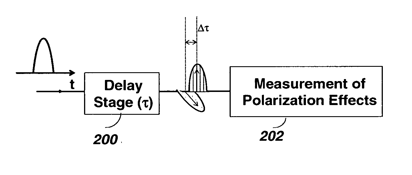
[0009] This invention includes novel autocorrelation techniques based on measurement of polarization effects of optical short pulses. The optical pulse is split into the two orthogonal polarization states and these two replicas have a relative delay which depolarizes the pulse. By tuning the relative delay of the two replicas and measuring the polarization characteristics of the pulse, the pulse's temporal width can be accurately derived.
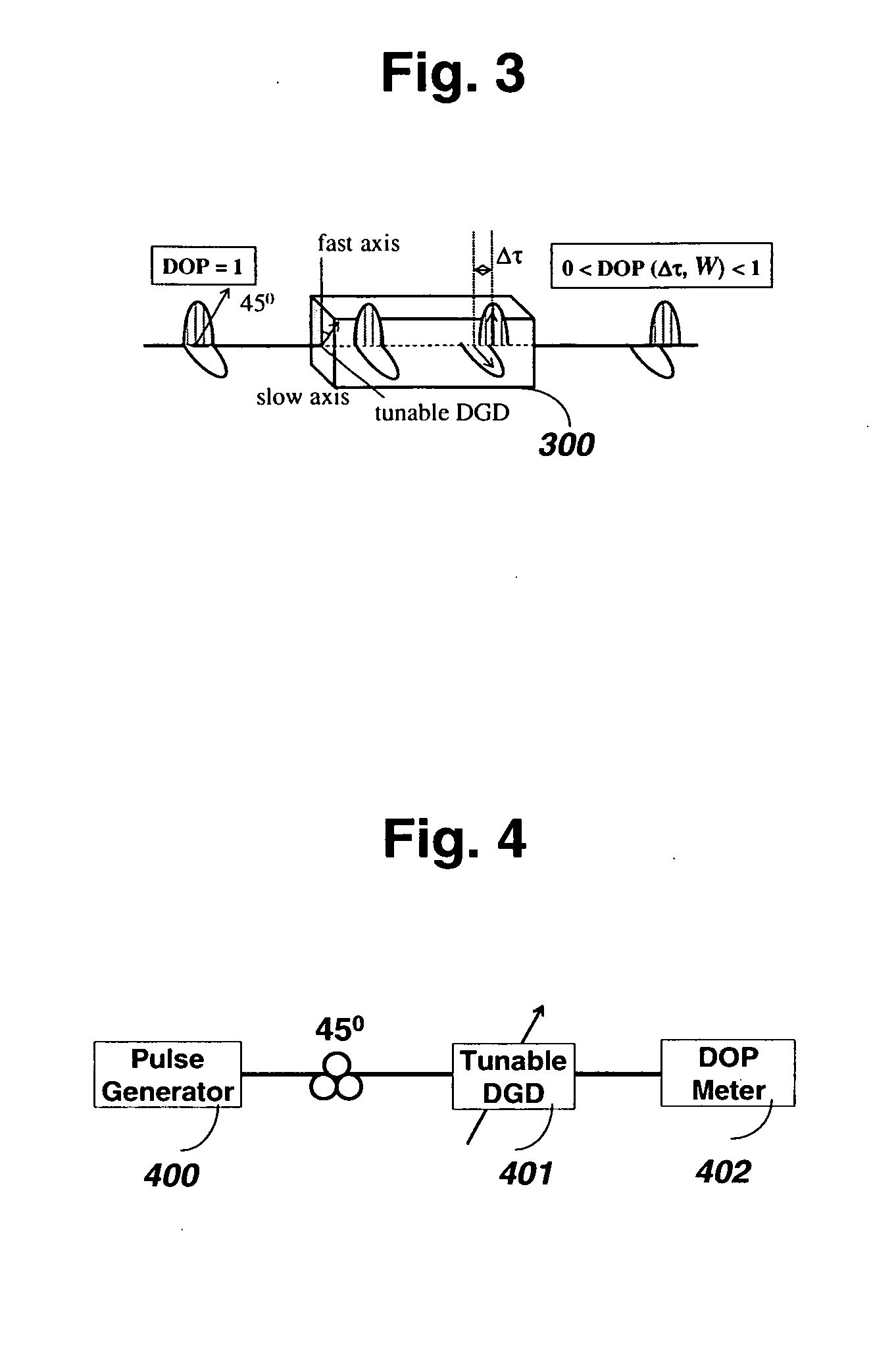
[0010] In one embodiment, the system consists of a tunable differential-group-delay (DGD) element and a simple degree-of-polarization (DOP) meter. While travelling in the tunable DGD module, the pulse is split equally into the two principal states of polarization (PSPs). The relative delay between these two polarization states is dynamically controlled via a computer interface. DOP of the output pulse is actually proportional to the autocorrelation function of the pulse and therefore is used to obtain the pulse width of the incoming signal. By measuring the DOP as a function of induced DGD, the pulse's temporal width can be accurately derived. This scheme is cost effective, wavelength independent, applicable to low optical power, all-fiber-based, and does not require significant optical alignment of free-space optical elements.

Problems solved by technology

A key drawback is that the operation usually requires significant alignment of the free-space optical components, and also amplification of the optical pulses to a high power level.

Method used


Image

  • Autocorrelation Technique Based on Measurement of Polarization Effects of Optical Pulses
  • Autocorrelation Technique Based on Measurement of Polarization Effects of Optical Pulses
  • Autocorrelation Technique Based on Measurement of Polarization Effects of Optical Pulses

Examples


Embodiment Construction

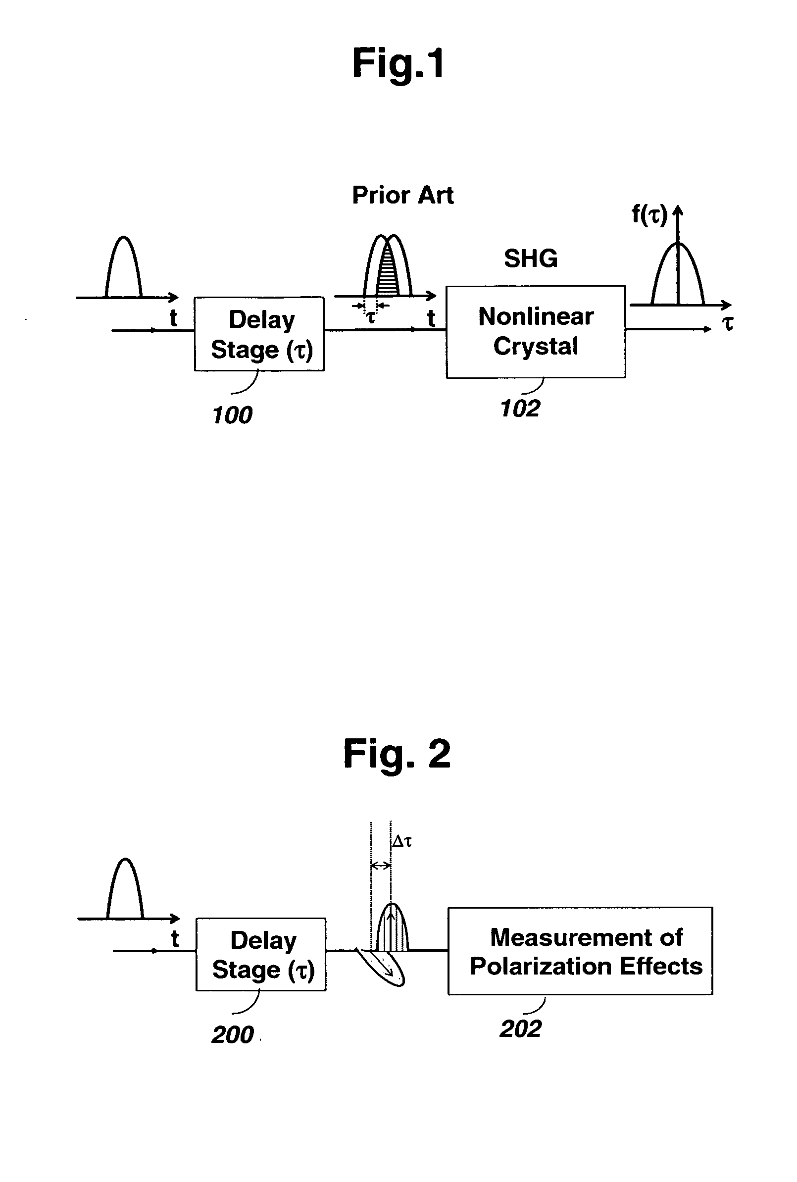
[0023] As shown in FIG. 1, in prior art, an incoming pulse is split in half by a free-space delay stage 100, with one half delayed relative to its twin. These two pulses impinge on a nonlinear crystal 102, for which a new optical signal is generated using second-harmonic generation (SHG) only where the two optical twin pulses overlap in time. The pulse width can then be derived by changing the time delay between the twin pulses. A key drawback of this typical configuration is that it requires a fair amount of alignment of the free-space optics. And the power of the input pulse should be high in order to induce nonlinear optical second-harmonic generation in the crystal.

[0024] In the present invention, as shown in FIG. 2, the optical pulse is split into the two orthogonal polarization components in a delay stage 200 and these two replicas have a tunable relative delay. The two replicas are combined after 200. By tuning the relative delay of the two replicas and measuring the polariz...


PUM


Abstract

Autocorrelation technique for measurement of width of optical short pulses based on polarization effects. The optical pulse is split into two orthogonal polarization states and these two replicas have a relative delay which depolarizes the pulse. By tuning the relative delay of the two replicas and measuring the degree-of-polarization (DOP) of the pulse or the induced polarimetric four-wave mixing (FWM) through nonlinear media, the pulse's temporal width can be accurately derived. The technique can be all-fiber-based, wavelength independent, cost effective, applicable to low optical power, and does not require significant optical alignment.

Description

CROSS-REFERENCE TO RELATED APPLICATIONS [0001] U.S. Patent Documents: 69566522005-10-18Whitbread et al.68474532005-01-02Bush et al.68194282004-11-16Ogawa et al.OTHER REFERENCES [0002] S. M. Reza Motaghian Nezam, et al, Journal of Lightwave Technology, Vol. 22, No. 3, pp 763-772, 2004 [0003] K. S. Chiang, et al, “Polarimetric four-wave mixing in a single-mode fiber,” IEEE Photonics Technology Lett., vol. 13, no. 8, pp 803-805, 2001 [0004] L.-S. Yan, et al “Programmable group delay module using binary polarization switching,” IEEE J. Lightwave Technol., vol. 21, no. 7, pp. 1676-1684, 2003 [0005] Parent Cast Text [0006] This Application claims the benefit of U.S. Provisional Application No. 60 / 659,026 and 60 / 659,853 filed Mar. 4, 2005, the entire disclosure of which is incorporated herein by reference as part of this application. BACKGROUND OF THE INVENTION [0007] High-speed optical communication systems in R&D facilities around the world have been steadily progressing to ever-higher ...

Claims


Application Information

Patent Timeline
Patent Type & Authority Applications(United States)
IPC IPC(8): G01J1/00
CPCG01J11/00
Inventor LUO, TINGYU, CHANGYUANPAN, ZHONGQIYAN, LIANSHANKUMAR, SAURABHWILLNER, ALANE
Owner UNIV OF SOUTHERN CALIFORNIA
Learn More